picmonkey122
Newbie level 4

- Joined
- Jul 10, 2014
- Messages
- 6
- Helped
- 0
- Reputation
- 0
- Reaction score
- 0
- Trophy points
- 1
- Activity points
- 43
Hi everyone,
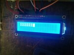
I have a problem with writing to a hitachi hd44780 16x2 display using the PIC16F1459. I have written several programs in C for this particular arrangement so I know from this that the wiring, LCD and PIC are all working correctly. I decided to switch over to writing in assembly because I wanted more control over the PIC. I am not a beginner with assembly would say I have a moderate understanding and have searched around a lot of forums and websites to better understand writing assembly for PIC's. However I cant seem to get the LCD to print out the correct characters. The code attached below initialises the LCD correctly - 16 boxes over 2 lines but when I want to write to it I can only get the LCD to print out strange characters (see attached photo).

I have a few ideas what might be wrong the obvious one is the LCD_Write subroutine also I'm wondering whether the PIC is correctly initialised. I would be grateful if you could look over the code.
Thanks.
I have a problem with writing to a hitachi hd44780 16x2 display using the PIC16F1459. I have written several programs in C for this particular arrangement so I know from this that the wiring, LCD and PIC are all working correctly. I decided to switch over to writing in assembly because I wanted more control over the PIC. I am not a beginner with assembly would say I have a moderate understanding and have searched around a lot of forums and websites to better understand writing assembly for PIC's. However I cant seem to get the LCD to print out the correct characters. The code attached below initialises the LCD correctly - 16 boxes over 2 lines but when I want to write to it I can only get the LCD to print out strange characters (see attached photo).

Code:
;***************************************
; date: Tue 8th July                    *
; version: 1.0                             *
; filename: LCD                          *
; PIC: p16f1459                         *
; clock frequency: 4MHz            *
; cty: 1 us                                 *
;**************************************

;=================
; Config Settings

        list    P=16f1459
        include "p16f1459.inc"

; CONFIG1
; __config 0x3FE4
 __CONFIG _CONFIG1, _FOSC_INTOSC & _WDTE_OFF & _PWRTE_OFF & _MCLRE_ON & _CP_OFF & _BOREN_ON & _CLKOUTEN_OFF & _IESO_ON & _FCMEN_ON
; CONFIG2
; __config 0x1FFF
 __CONFIG _CONFIG2, _WRT_OFF & _CPUDIV_CLKDIV6 & _USBLSCLK_48MHz & _PLLMULT_3x & _PLLEN_ENABLED & _STVREN_ON & _BORV_LO & _LPBOR_OFF & _LVP_OFF


;======================
; Declarations

#define     LCD_PORT    LATC
#define     LCD_RS      LATC,4
#define     LCD_E       LATC,5

; RW is grounded
; D4 ----> RC0
; D5 ----> RC1
; D6 ----> RC2
; D7 ----> RC3

;=====================
; Variable Definitions

        cblock  H'20'
        count
        delay_1
        delay_2
        delay_3
        tempLCD
        endc

;==============
; Reset Vector

        org   0x0000
        goto  Start

Init
;====================
; Disable comparators

        bcf     CM1CON0,C1ON    ; clear C1ON
        bcf     CM2CON0,C2ON    ; clear C2ON

;========================
;Set Oscillator frequency

        banksel OSCCON
        movlw   B'11110111'     ; 4MHz internal oscillator ; cty = 1us
        movwf   OSCCON

        banksel TRISC           ; select LCD bus
        movlw   B'00000000'     ; all pins output
        movwf   TRISC

        banksel LATC
        clrf    LATC
        banksel ANSELC
        clrf    ANSELC

        ; initialisation delay - 1 sec
        movlw   D'100'
        call    delay_long

        return

;============================================
; Delay subroutine which lasts for 100 * cty

delay_long
        movwf   delay_3
delay_long_loop2
        movlw   D'13'
        movwf   delay_2
        clrf    delay_1
delay_long_loop1
        decfsz  delay_1,f
        goto    delay_long_loop1
        decfsz  delay_2,f
        goto    delay_long_loop1
        decfsz  delay_3,f
        goto    delay_long_loop2

        return

;=========================
; Delay subroutine 10 * cty

delay_short
        movwf   delay_2
delay_short_loop2
        movlw   D'249'
        movwf   delay_1
delay_short_loop1
        nop
        decfsz  delay_1,f
        goto    delay_short_loop1
        decfsz  delay_2,f
        goto    delay_short_loop2

        return

;==================
;LCD Initialisation

LCD_Init
        banksel LATC
        bcf     LCD_RS          ; commands so RS bit low

        movlw   D'16'
        call    delay_short
        banksel LATC
        movlw   0x03
        movwf   LCD_PORT
        call    Nibble
        movlw   D'6'
        call    delay_short
        banksel LATC
        movlw   0x03
        movwf   LCD_PORT
        call    Nibble
        movlw   D'1'
        call    delay_short
        banksel LATC
        movlw   0x03
        movwf   LCD_PORT
        call    Nibble
        movlw   D'5'
        call    delay_short

        banksel LATC
        movlw   0x20            ; set 4 bit mode
        movwf   LCD_PORT
        call    Nibble
        movlw   0x28            ; 2 lines, 5 x 7 font
        call    LCD_Cmd
        movlw   0x08            ; display switch: D = 0, C = 0, B = 0
        call    LCD_Cmd
        movlw   0x0F            ; display switch: D = 1, C = 1, B = 1
        call    LCD_Cmd
        call    LCD_Clear       ; clear display
        movlw   0x06            ; input set: I/D = 1, S = 0
        call    LCD_Cmd


        return

;============
; Send nibble

Nibble
        banksel LATC
        bsf     LCD_E           ; high
        movlw   D'1'
        call    delay_short
        banksel LATC
        bcf     LCD_E           ; low
        movlw   D'2'
        call    delay_short

        return

;============
; LCD Command

LCD_Cmd
        movwf   tempLCD
        swapf   tempLCD         ; higher nibble to W
        movfw   tempLCD
        andlw   0xF0
        banksel LATC
        bcf     LCD_RS          ; RS set low due to instruction write
        banksel LATC
        movwf   LCD_PORT
        call    Nibble
        movlw   D'2'
        call    delay_short

        swapf   tempLCD         ; lower nibble to W
        movfw   tempLCD
        andlw   0xF0
        banksel  LATC
        bcf     LCD_RS
        banksel LATC
        movwf   LCD_PORT
        banksel  LATC
        bcf     LCD_RS
        call    Nibble
        movlw   D'10'
        call    delay_short

        return

;==========
; LCD Write

LCD_Write
        movwf   tempLCD
        swapf   tempLCD         ; higher nibble to W
        movfw   tempLCD
        andlw   0xF0
        banksel LATC
        bsf     LCD_RS          ; RS set high due to data write
        banksel LATC
        movwf  LCD_PORT
        call   Nibble
        movlw   D'2'
        call    delay_short

        swapf   tempLCD         ; lower nibble to W
        movfw   tempLCD
        andlw   0xF0
        banksel LATC
        bsf     LCD_RS
        banksel LATC
        movwf   LCD_PORT
        call    Nibble
        movlw   D'10'
        call    delay_short

        return

;===========
; LCD line 1

LCD_Line1
        movlw   0x80
        call    LCD_Cmd

        return

;===========
; LCD line 2

LCD_Line2
        movlw   0xC0
        call    LCD_Cmd

        return

;==============
; Clear Command

LCD_Clear
        movwf   0x01
        call    LCD_Cmd

        return

;=============
; Program main
Start
        call    Init
        call    LCD_Init

Main
        movlw   0x50        ;P
        call    LCD_Write
        movlw   0x49        ;I
        call    LCD_Write
        movlw   0x43        ;C
        call    LCD_Write
        goto    $           ; loop forever

        end
I have a few ideas what might be wrong the obvious one is the LCD_Write subroutine also I'm wondering whether the PIC is correctly initialised. I would be grateful if you could look over the code.
Thanks.


