Continue to Site

Welcome to EDAboard.com

Welcome to our site! EDAboard.com is an international Electronics Discussion Forum focused on EDA software, circuits, schematics, books, theory, papers, asic, pld, 8051, DSP, Network, RF, Analog Design, PCB, Service Manuals... and a whole lot more! To participate you need to register. Registration is free. Click here to register now.

Are 220 V to 110 V voltage converters safe?

Status
Not open for further replies.
Hi,

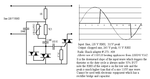
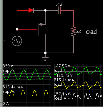
When you use a diode to half wave rectify a 220V RMS sine you get a 155V RMS signal.

Additionally there is a DC component that may harm some devices...

Klaus
 

The 220 -> 110 V converter for non electronic appliances is likely with thyristors like in the attached schematic.
 

Attachments

  • Converter 220V 110V thyristors.png
    Converter 220V 110V thyristors.png
    4.9 KB · Views: 71

A hair dryer has likely an AC motor. If a cheap converter rectifies AC into DC then how does the motor work?

Hair dryers tend to use DC motors which are more efficient and lower cost.
I've seen 1N4005 diodes inside mine.
However commercial tools that are heavy ,ay be using AC motors.

But the link comparing the two had this fallacy,
"Oh yes, by the way . . . Wattage has nothing to do with the volume of airflow nor does it reflect the heat output. "

Watts consumed translates in power consumed in both moving air and heat generated.
The fan may be 50 Watts (vs 5W for a muffin fan), the heat make be up to 1500W so heat is the dominant figure.
 

The main idea is that the output of a 220 -> 110 V voltage converter can not be a rectified half sine simply because there are various electric devices (appliances) that use AC electric motors and they will not work with a voltage having such a profile.

The output of the converter must have both a positive and negative part like in the picture I attached to my previous post.


I would agree as long it is not the same in your first post.
ElectricityConverted-520.jpg


The figure above would only work for hair dryers with DC motors in the "right " polarity.
 

It is the author John Bermont the one who says the converted 220 - 110 V looks like a rectified half sine, not me. I have doubted this from the beginning.

The output of the converter should have a positive and negative part like in this schematic (see: https://kakopa.com/PSA220-110/index.html) and not as in the diagram of John Bermont, an author that in my opinion wrote in his book a mixture of outdated things (like the problem US electric clocks could have in Europe) and wrong information as is the case with his rectified half sine. There could have been some old converters that generated a half 110 V sine from a 220 AC and were designed for lamps, heaters, etc. but this does not mean that the majority of converters work like this.

The online book of John Bermont is quite visible on the net and the likelihood to find it, while searching for information related to 220 -> 110 V converters, is high, just to find there, written in an apparently professional style, dubious, inaccurate things that mislead the reader.
 

You can power a 110Vac motor off 220Vac by using a suitably sized capacitor in series to drop half of the volts, if you know the normal motor current say 400mA, divide this into 110Vac to get the impedance = 1 / (2. pi. Freq. C) and hence get C, for 400mA C = 11uF (50Hz), which might be overly large for your application, other solution is to use a triac regulator off the 220Vac to power the motor, this will work OK and is small, but needs a small heatsink for the triac...
 

if you know the normal motor current say 400mA, divide this into 110Vac to get the impedance = 1 / (2. pi. Freq. C) and hence get C, for 400mA C = 11uF (50Hz)
A 110 V hairdryer or a drill can have a few speeds and for each the motor will need a different current.
 

A 110 V hairdryer or a drill can have a few speeds and for each the motor will need a different current.

Your device is basically a dimmer, using a triac to conduct half the wave. The "transformer" inside is a coil to help reduce the peaks.
This device is ok for light bulbs or electric motors, it is too risky for electronics because the peaks of the cut off sine are about 200V.
You can get 2KW out of it as the specs with no problem.
It is not an isolating transformer and you cannot use is as a safety transformer in a construction site.
If you want to make one, get a dimmer and replace the pot for a resistor that will give you 110V.
 
Last edited:

The half-wave rectification idea might be put to use as a way to reduce 220VAC for use by appliances designed for 120VAC.

I don't know how feasible this is, but such an adapter could fit into a tiny space.


Notice the half-wave Ampere waveform from the AC supply. The single diode does this.

The capacitor passes the waveform as AC only.
The mosfet turns on during the negative part of the cycle. It acts to discharge the capacitor backwards through the load.

The load gets a lopsided waveform, however it is at half of the incoming voltage.
This is done without a transformer.
 

Status
Not open for further replies.

Part and Inventory Search

Welcome to EDABoard.com

Sponsor

Back
Top