SthAusGuy
Newbie level 5
- Joined
- Jan 7, 2012
- Messages
- 8
- Helped
- 3
- Reputation
- 6
- Reaction score
- 3
- Trophy points
- 1,283
- Location
- Adelaide, South Australia, Australia
- Activity points
- 1,355
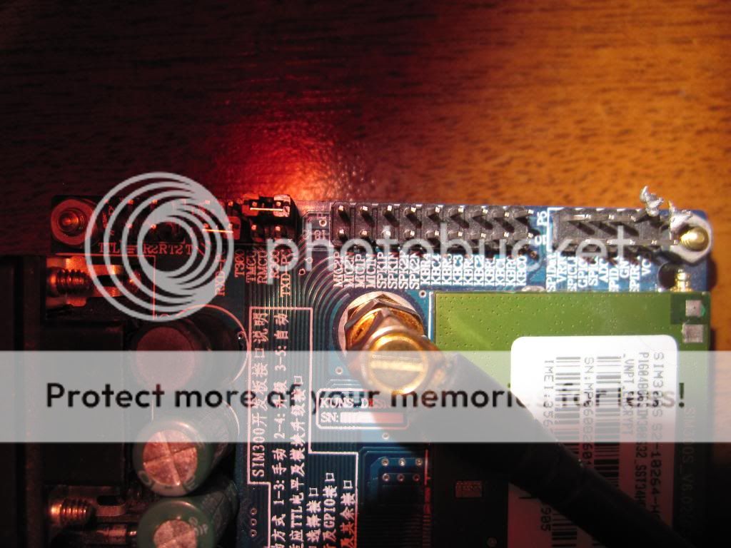
Yes, the green LED (NET) comes on for a few moments on power ON. Then the red SYSTEM LED stays on as the SIM300 boots up.
After receiving the "CALL READY" the green NET light flashes slowly (Every couple of seconds or so).
When I call, the RING LED comes on as expected.
What do the LEDs display on your's sahancr? If it does something completely different could you make a quick vid of the boot up sequence.
It's crazy. Even though I can't get this board up and running, it looks like a great component for such a low price. I'm tempted to unsolder the SIM300 and check the connections underneith.
I've contacted the seller in case he knew it was defective (It was second hand afterall) but as usual they give you the run around!