Continue to Site

Welcome to EDAboard.com

Welcome to our site! EDAboard.com is an international Electronics Discussion Forum focused on EDA software, circuits, schematics, books, theory, papers, asic, pld, 8051, DSP, Network, RF, Analog Design, PCB, Service Manuals... and a whole lot more! To participate you need to register. Registration is free. Click here to register now.

Anti log amplifier help?

Status
Not open for further replies.

neazoi

Advanced Member level 6
Joined
Jan 5, 2008
Messages
4,122
Helped
13
Reputation
26
Reaction score
15
Trophy points
1,318
Location
Greece
Activity points
36,951
I would like to see if it is possible to design an anti-log (exponential) HF preamplifier.
One idea might be a conventional amp with a log amp in the feedback loop.
Can anyone with simulation skills or good ideas help me in that direction?
I love discrete transistors circuits, if this can be done that way.


Regards, Dana.
Excellent book the last one!
Actually this "Dead Zone" in part1 Basic operations pp25 of the book, might be useful, as it has thresholds that can be set. It is not an exponential amplifier, but it will do in my case, as it does not amplify signals under a certain signal level, if I am getting this right.
A circuit is given with opamps but I have no idea of the starting values for HF (2-30MHz) or what opamps to use for these frequencies.
--- Updated ---

Excellent book the last one!
Actually this "Dead Zone" in part1 Basic operations pp25 of the book, might be useful, as it has thresholds that can be set. It is not an exponential amplifier, but it will do in my case, as it does not amplify signals under a certain signal level, if I am getting this right.
A circuit is given with opamps but I have no idea of the starting values for HF (2-30MHz) or what opamps to use for these frequencies.
UPDATE:
But how the dead zone circuit will behave under the presence of a strong amplitude sine in one frequency and a very low amplitude signal on another frequency? At the time that the amplifier conducts, it would amplify both signals, isn't that true?

On the other hand, an exponential amplifier will amplify both signals too, but at all times. It just amplifies the larger signals more than the lower.
 
Last edited:

Sounds like you didn't actually consider your requirements.
1. anti-log is has an unipolar characteristic with output >0, not suited for AC signals, e.g. RF
2. it has a strongly nonlinear characteristic. If you feed two signals to it, it acts as a mixer and doesn't maintain the original input spectrum
 

    neazoi

    Points: 2
    Helpful Answer Positive Rating
Can you describe a bit more what your intended circuit is for ?
Eg. what is input signal, its characteristics, and what processing
do you want done on that, eg. goal of output.

The circuit you are looking at is a summation of two signals
processed linear over region outside dead zone, followed by
simple sum of them. So not antilog....?

1677930439618.png


What is the GBW you need for the signal path ? That will determine OpAmp
choice. Given you will be working in RF range you will need very careful layouts'
and power distribution. Datasheets for these types of OpAmps have strong layout
recommendations for the respective OpAmp that one should follow. Will you be
working in a 50 ohm environment ?

Attached additional reference that you might find useful.

Lastly here is a table of wideband OpAmps, take a look at a couple of datasheets
to get an idea of layout considerations. if, for example, you want a G of ten in the
signal path, and you want 30 Mhz 3 db kinds of response, you need to look at parts
whose GBW > 300 Mhz. I have worked with OpAmps in this area (hybrids) eons ago
and they were a beast to stabilize. Even capacitors were a problem, careful selection/
evaluation needed for them as well.


Regards, Dana.
 

Attachments

  • Log and Antilog Amplifier - Amit Degada.pdf
    1.1 MB · Views: 82
Last edited:

    neazoi

    Points: 2
    Helpful Answer Positive Rating
Sounds like you didn't actually consider your requirements.
1. anti-log is has an unipolar characteristic with output >0, not suited for AC signals, e.g. RF
2. it has a strongly nonlinear characteristic. If you feed two signals to it, it acts as a mixer and doesn't maintain the original input spectrum
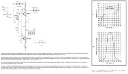
Both statements are very useful to know, thanks. I suspected about the second. See this image, I have taken it out of a Tektronix 491. This represents the square law position where the differences between smaller and larger signals are shown larger. This does work on RF, but I do not remember where the filter is, before or after it, I have to look at it.
Perhaps there is a filter before, just to minimize the 2nd case you refer to.
--- Updated ---

Can you describe a bit more what your intended circuit is for ?
Eg. what is input signal, its characteristics, and what processing
do you want done on that, eg. goal of output.

The circuit you are looking at is a summation of two signals
processed linear over region outside dead zone, followed by
simple sum of them. So not antilog....?

View attachment 181579

What is the GBW you need for the signal path ? That will determine OpAmp
choice. Given you will be working in RF range you will need very careful layouts'
and power distribution. Datasheets for these types of OpAmps have strong layout
recommendations for the respective OpAmp that one should follow. Will you be
working in a 50 ohm environment ?

Attached additional reference that you might find useful.

Lastly here is a table of wideband OpAmps, take a look at a couple of datasheets
to get an idea of layout considerations. if, for example, you want a G of ten in the
signal path, and you want 30 Mhz 3 db kinds of response, you need to look at parts
whose GBW > 300 Mhz. I have worked with OpAmps in this area (hybrids) eons ago
and they were a beast to stabilize.


Regards, Dana.
Yes, this is the circuit I was looking from that book. Input level can be as low as a few uV (-100dbm or so) and as high as -10dbm, even more. Frequency is 2-30MHz. I do not need much gain, 3-9db at max I think should be more than enough. I bet the same thing can be done with simple BJTs as amplifying elements instead of the opamps (I may be wrong though).
 

Attachments

  • exponential amp tek491.PNG
    exponential amp tek491.PNG
    188.2 KB · Views: 73
Last edited:

Then simple CE designs would suffice, maybe a CB front end for Z translation if
you need that. Followed by a summer. But the dead zone behavior not sure
how to tackle that with simple discrete approach.

Here is a classic Motorola ap note - https://cdn.macom.com/applicationnotes/AN215a.pdf

Since you want 1 uV on low end makes one wonder if a dual gate MOSFET might
give you some flexibility in design/dead band......


Regards, Dana.
Thanks a lot.
What puzzles me is how will such a dead-zone circuit will behave under the presence of a strong amplitude sine in one frequency and a very low amplitude signal on another frequency? At the time that the amplifier conducts, it would amplify both signals, the high one but also the low one, isn't that true?
The amplifier sees input signal levels. Once it is triggered by the presence of the high level signal, it will also amplify the low level one.
In contrast, an exponential amplifier just amplifies differently, low and high level signals.
I hope I understand the above things correctly?
 

In the circuit you are interested in each signal processed with an amp with dead band
before summation. So the low level signal, if its amplitude in the dead band, does not
get passed. 1 uV I would posit is right at noise levels in circuit, so not sure what region
of it you want "dead banded".

Basically you have two linear amps, with the special property of dead band region, being
summed. And the low level signal close to or in noise region when it is out of dead band
region.

I think you need to do some simulations to get a handle on this, at the least a starting
point.


Regards, Dana.
 

Diode voltage-versus-Amperes curve. Exponential.

silicon diode V-vs-A curve exponential.png


I once tested real diodes, reading volts and Amps. I graphed the data then finagled with equations in a search for a formula I could use in my homebrew simulator. (I steered away from the Shockley formula.) This reasonable match emerged:

A=(V * 1.25)^20
 

Diode voltage-versus-Amperes curve. Exponential.

View attachment 181586

I once tested real diodes, reading volts and Amps. I graphed the data then finagled with equations in a search for a formula I could use in my homebrew simulator. (I steered away from the Shockley formula.) This reasonable match emerged:

A=(V * 1.25)^20
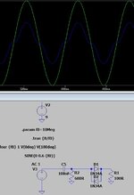
Or a set of anti parallel ones, as used in the Tek 491. The problem with such approaches is the high signal level used. Anyway, here is the anti parallel diodes simulation.
 

Attachments

  • 11.JPG
    11.JPG
    52.3 KB · Views: 67

Status
Not open for further replies.

Similar threads

Part and Inventory Search

Welcome to EDABoard.com

Sponsor

Back
Top