Continue to Site

Welcome to EDAboard.com

Welcome to our site! EDAboard.com is an international Electronics Discussion Forum focused on EDA software, circuits, schematics, books, theory, papers, asic, pld, 8051, DSP, Network, RF, Analog Design, PCB, Service Manuals... and a whole lot more! To participate you need to register. Registration is free. Click here to register now.

Ansoft Maxwell vs. CST EMS

Status
Not open for further replies.

jpsmith123

Full Member level 2
Joined
Dec 5, 2002
Messages
137
Helped
4
Reputation
8
Reaction score
1
Trophy points
1,298
Activity points
1,070
ansoft vs. cst

Just in case anyone else is interested...

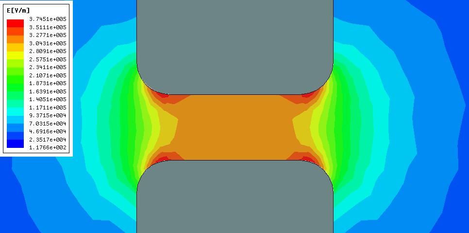
Well I decided to make a spark gap switch using some round graphite rod material for electrodes, and I wanted to see what the E-field would look like, i.e., what kind of field enhancement would result if I merely rounded the edges to a 0.125" radius (using a form tool in a lathe), so I simulated it using CST EMS 2009, and for comparison, Ansoft Maxwell 2D v12.1.

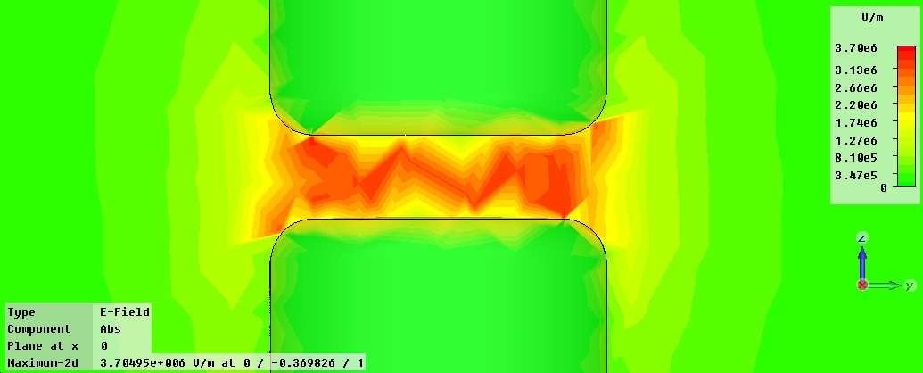
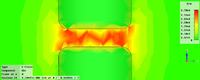
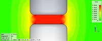
As expected, the CST scalar field plot is an unintelligible mess (using the default settings) whereas the default Ansoft field plot seems reasonable and informative.

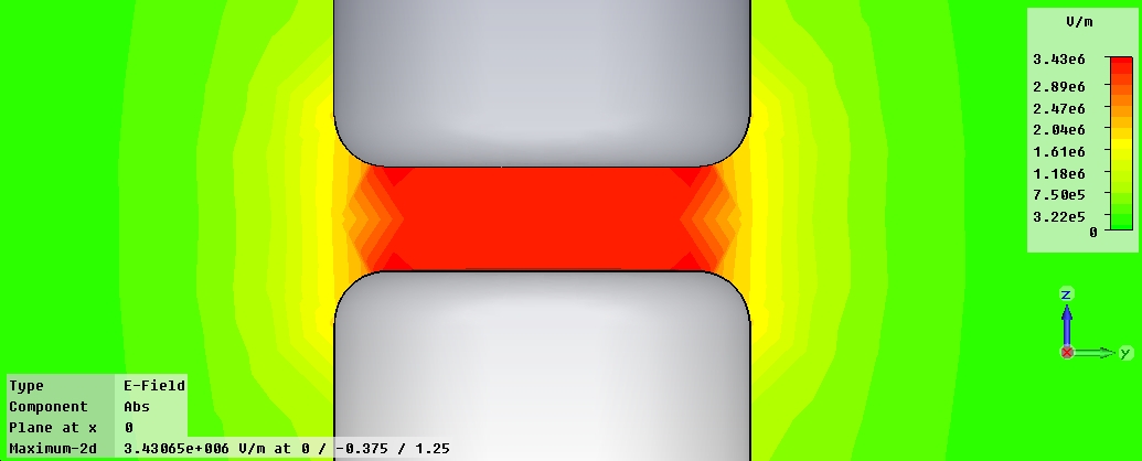
Granted that the CST field plot can be improved somewhat by making the mesh finer and adjusting the "plot properties", particularly the "scaling", but even at its best, the CST plot seems highly artifactual and less useful than the Ansoft result.

I wonder, is CST EMS really this useless for such a simple electrostatic problem, or am I doing something wrong?

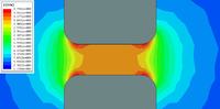
I will attempt to attach images of the several field plots to this post. The first is the Ansoft Maxwell plot, followed by CST EMS, first using tetrahedral mesh and then hexahedral mesh.


maxwell plotting fields

Just to follow up on this in the event someone else is interested, the CST 2D scalar plots can apparently be improved by creating a "dummy" vacuum region around the geometry of interest, and then adjusting the local mesh properties of the vacuum region to get a finer mesh, and then increasing the plot quality under "plot properties" -> "specials". In order to get the most useful Efield plot, it seems you will always need to experiment with the "scaling" to make sure the finer features of interest are visible.
 

Hello

I'm studying field radiated from spark discharge (air gap) by using CST simulation. i don't understant how to use this program for simulate this phenomena. If you don't mine, may you give me some suggestion.

best regards
 

Are you talking about a "frozen wave generator" of some sort, e.g., where you have a spark gap switch between two charged conductors above a ground plane, and when the spark gap fires, the conductors radiate a high power RF pulse whose wavelength depends on the length of the conductors?

Or is the spark gap itself supposed to be the antenna?
 

Thank you for answer my question

My work is field radiation form arcing in gold ball bond (GBB) process. GBB process is a process for connecting electrical leads. In this process, a high voltage (4 kV) is periodically applied to a wand which then arcs to a tip of gold wire.


How electric field, magnetic field and electromagnetic field generated from arcing between EFO wand and the tip of gold wire? What waveform are they look like?

How to use CST programe to simulate this event?

Best regard

Reference (Picture)
[1] Jeng-Cheng A. Chen, Chung - LI, "Electric Flame-Off Wand,"patent,1997.
[2] Kuan-Jung Chung, Joseph B. Bernstein,Liyu Yang, "Experimental Study of EFO Ward Electrode Wear, Surface Pollution, and Discharge Gaps in Wire Bonding Process," Tamkang Journal of Science and Engineering, Vol. 6, No. 1, pp. 43-48,2003.
 

Hi all, i am studying the spark which generated by non-contacted ESD, and i want to simulate it in Ansoft Maxwell. I saw a solution on Ansoft website, but it's just a result, without details to describe how to get it. Anyone can tell me how to build the model. For the current, resistor of the spark changed with time, how can I represent this in the software? Or CST may do this?
 

Hmmm, I don't really know what to tell you, but let me think out loud: Maybe you'll be using a discreet voltage or current port to drive an arrangement of conductors
with a geometry representative of the physical situation? And the main question is, what should the excitation pulse look like?

Once the spark gap is fully conducting, with the exception of a fixed voltage drop of 150 volts or so, it's just like a piece of wire, with an inductance of maybe 10
nH/cm or so, and a few milliohms of resistance. So I suppose the important thing is how fast it switches, i.e., di/dt. (I will try to find a paper I have around here
somewhere which discusses the physics of spark gap switching).

Anyway, IIRC, spark gap di/dt is ultimately limited by both an inherent resistive component, and the inherent inductance of the device, but the question is, what does the rest of the circuit look like? Is it just a capacitor charged up through a resistor, discharging through a self-breaking spark gap to ground? It may be that the inductance of the external circuit swamps out the spark gap.

If you knew what the circuit looked like electrically, maybe you could get an idea what the voltage and/or current waveforms would look like using a spice simulator, maybe that would be a starting point?
 

Thank you very much

I am looking for information about arc resistance and arc inductance electrical model as you suggest.

best regard
 

I think first of all you should study more about arc discharges. This process is highly dependent on electrode distance and voltages. This phenomena usually have a transient regime which the ionizing atmosphere goes stable. In this regime the impedance reduces to a low value and current goes up. But if your voltage source is capacitive or ac voltage is applied, this stability is short in time. The source voltage drops and the arc regime goes off. In a very simple look, if you can find the current vs. time you may be can estimate the propagating wave. Apply this current source to an antenna which looks like the arc shape between your electrodes, and start the transient solver. May be current measurement is practical in laboratory.
But more realistically you should define a electron emission source and an ionizing medium to find the accurate model of this discharge. CST PS is not capable of model the ionizing medium, but for example MAGIC can. Finally it should be noted that almost all discharge types are not cold plasma, and PIC solvers are applicable to only cold plasma mediums.

Find more about discharge on 'Industrial Plasma Physics Volume 1, by A. Roth'
 

Well I found the paper I was looking for, but it's a chapter from a book. It's a chapter from the book "High-Power Electronic Systems". If you want it I could PM it to you.

carrotparadise said:
Thank you very much

I am looking for information about arc resistance and arc inductance electrical model as you suggest.

best regard
 

To jpsmith123,

Hello, I was very much interested by a problem about arc modelling in a spark gap. How you have simulated an arc in Maxwell? If it is possible, send please an source file (arccos@gmail.com).

Best regards
 

Status
Not open for further replies.

Part and Inventory Search

Welcome to EDABoard.com

Sponsor

Back
Top