Vermes
Advanced Member level 4
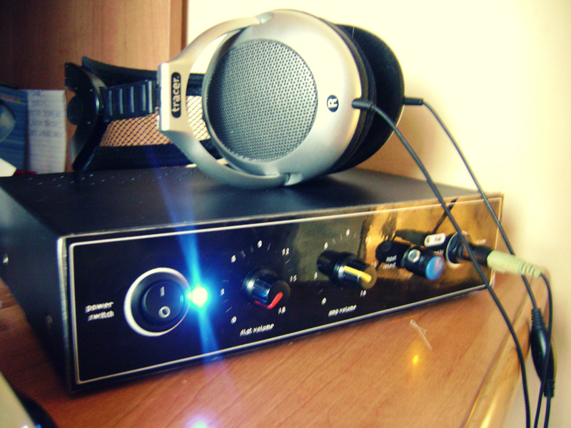
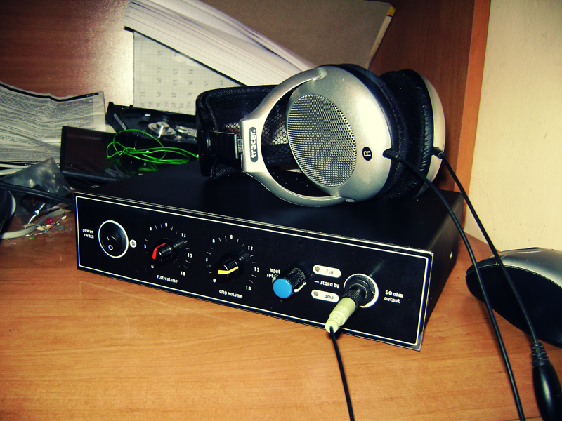
It is a design of class A headphone amplifier. It uses kit AVT2464, which is based on MOSFET transistors. There are two versions of the schematic: one with additional reinforcement on the other transistor and the second giving the signal directly to the gate of main transistor. This construction involves a switch for switching between those two versions.
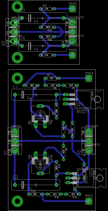
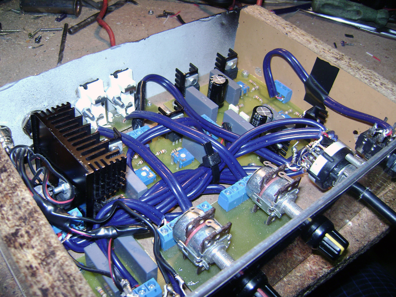
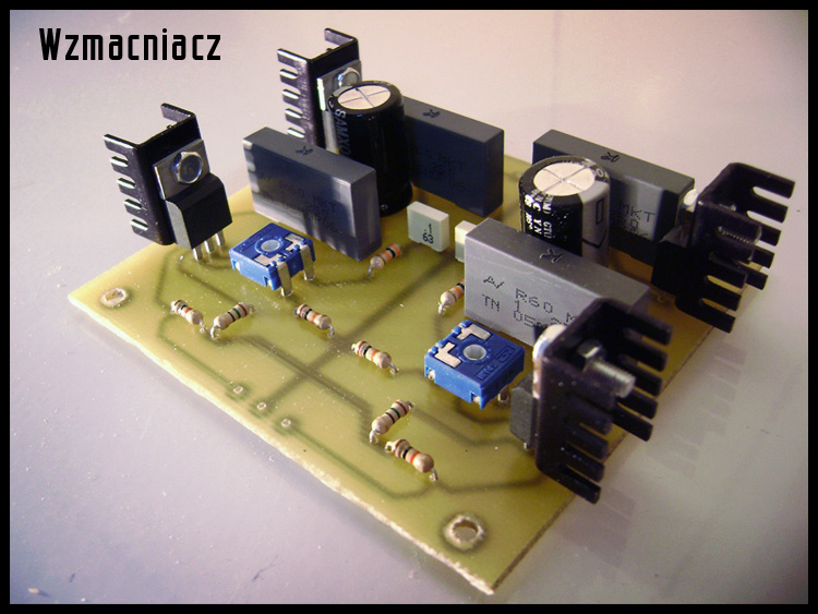
PCB of the main part:

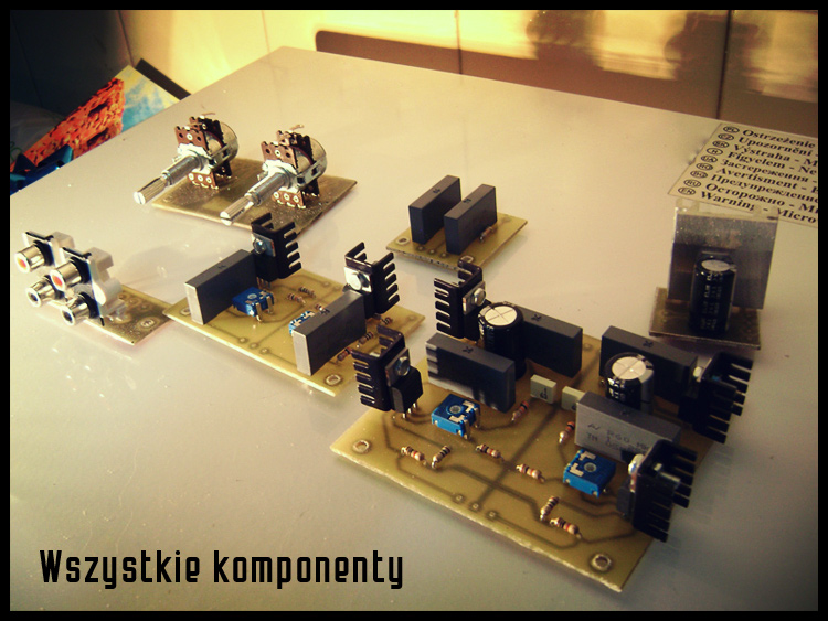
PCB of input parts - version without (up) and with reinforcement (down):
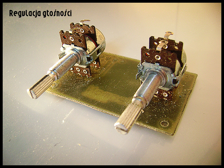
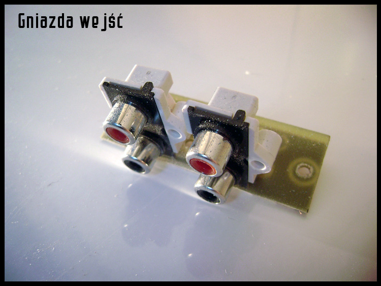
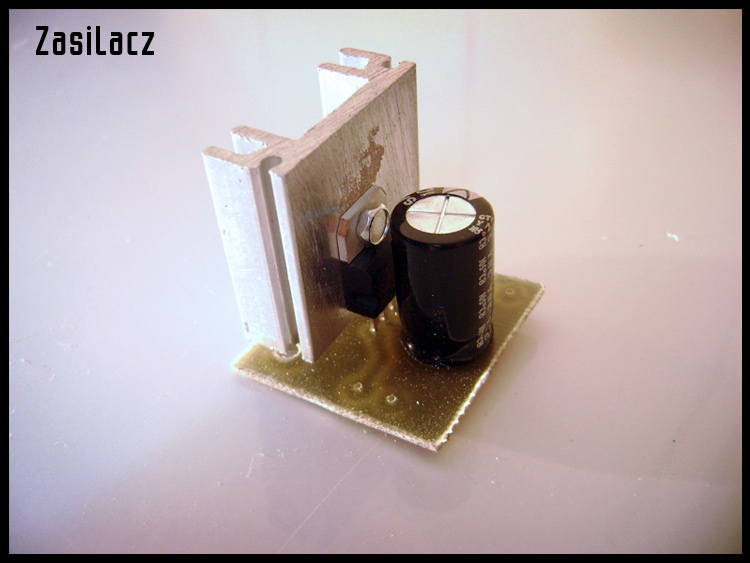
You have to make a PCB for input sockets, volume adjustment potentiometers and power supply (classic system of a bridge, capacitor, stabilizer and again capacitor).
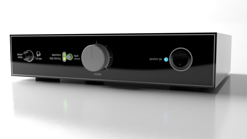
You can also create the design and visualization of the housing in a program for 3D graphics:
The PCBs were made in thermal transfer method.
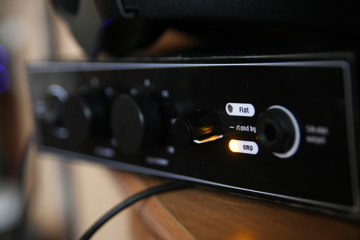
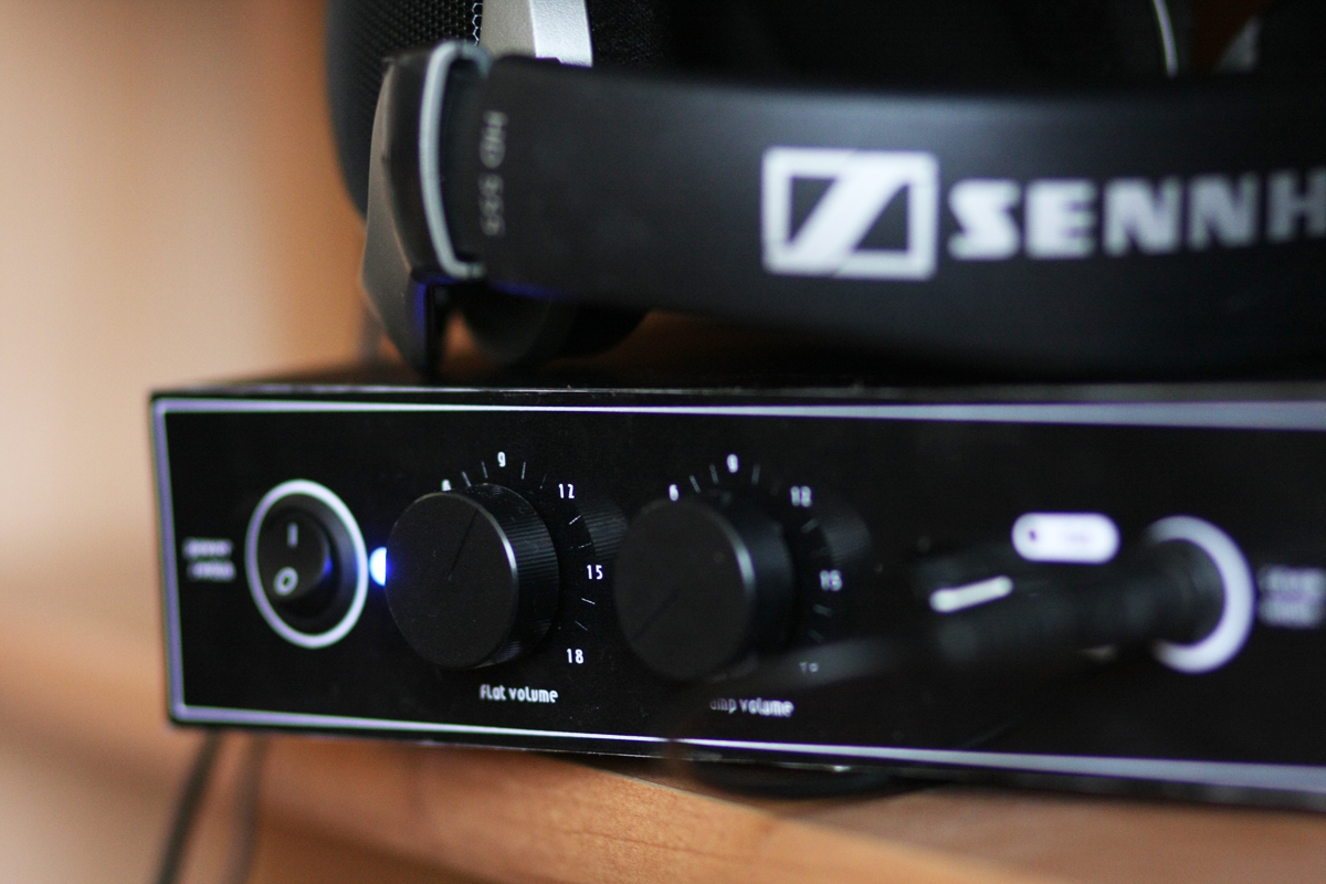
The main exception to the schematic of AVT kit was cutting its two versions and joining with three-position three-sectional rotary switch. It was enough to switch between the two channels independently and to provide power to one or another input PCB. That is why the amplifier has two separately adjustable inputs, which can be switched at any moment. The middle position of the switch is similar to Standby mode, because in that position voltage is not provided to any of input PCBs nor to the main PCB. All grounds (supply, signal) are connected to the switch, so when you disconnect it, ground does not contact the main part.
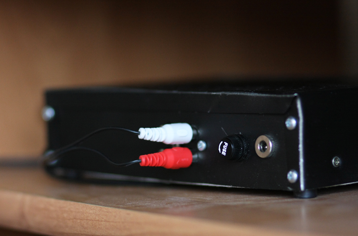
The amplifier is supplied by a standard power supply. It consists of two parts: first of them is placed in a separate housing with transformer 18V 1,2A, bridge and filtering capacitor. Then a cable derives the initial voltage to the housing of the amplifier, where it is processed by stabilizer, which reduces too high voltage (measured 28V) to required 15V and heats up significantly while doing that. It uses a part of heat sink from an old processor.
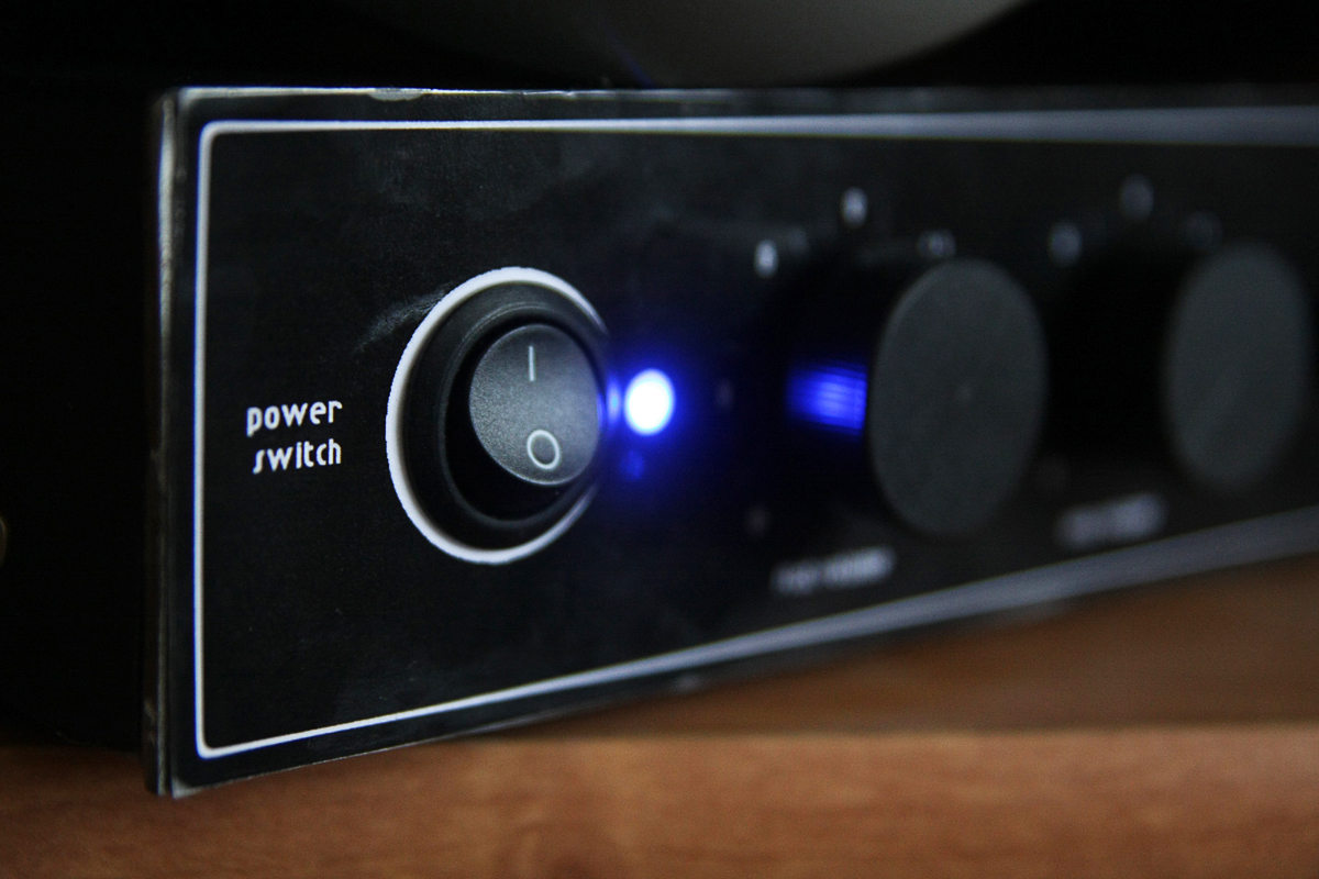
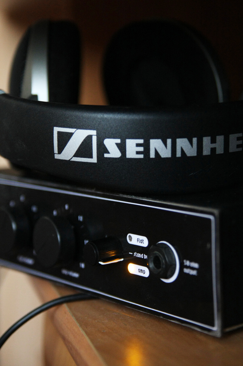
Base of the housing was made of fibreboard and two pieces of chipboard which hold the whole. Front panel made of 3mm thick flat bar is screwed to it. Top is made of steel sheet bent and drilled to provide ventilation. The sheet was painted with black spray. Plate for the back wall was removed from a computer housing. Description on the front panel was made in a graphical program and printed, then laminated and glued to the flat bar using aquarium silicone.
Components in the housing are linked together with 2-wire shielded cable, where the shield acts as the ground.
Pictures:


Link to original thread (useful attachment) - Wzmacniacz słuchawkowy klasy A