Continue to Site

Welcome to EDAboard.com

Welcome to our site! EDAboard.com is an international Electronics Discussion Forum focused on EDA software, circuits, schematics, books, theory, papers, asic, pld, 8051, DSP, Network, RF, Analog Design, PCB, Service Manuals... and a whole lot more! To participate you need to register. Registration is free. Click here to register now.

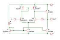
Analysis of given circiut?. is it an OPAMP? explain if you answer is yes.

Status
Not open for further replies.

Moazza Sultan

Newbie level 5
Joined
Apr 9, 2013
Messages
10
Helped
0
Reputation
0
Reaction score
0
Trophy points
1,281
Activity points
1,334
check.png

Explain the given Circuit. is it an OPAMP?
Where's the input stage and output stage?
 

is it an OPAMP?
No, it's not.

To turn it into an opamp:
  • Remove Q7 from the circuit.
  • Connect the collector of Q8 to the collector of Q9 and the output.
  • Disconnect the base of Q8 from the bases of Q5 and Q6, and connect it to the collectors of Q2 and Q6 instead.
 

Looks like a partly failed attempt to design an OP. Only input stage Q1/Q2 is working, output stage Q7 is not working, it's permanently in saturation, providing no gain.
 

To turn it into an opamp:
  • Remove Q7 from the circuit.
  • Connect the collector of Q8 to the collector of Q9 and the output.
  • Disconnect the base of Q8 from the bases of Q5 and Q6, and connect it to the collectors of Q2 and Q6 instead.

    Why should i do all that ? reasons?
    I need to explain them to my teacher.

    I try the changes you mention, but Vbe of Q8 becomes 0.44 V

    - - - Updated - - -

    What are the necessary things to design the OPAMP?

    - - - Updated - - -
 

After making the changes, the circuit should look like this:


Why should i do all that ?
To fix the circuit.

Because the circuit you showed doesn't work.

I try the changes you mention, but Vbe of Q8 becomes 0.44 V
Maybe you ran the simulation with no input and no feedback. The circuit has a small DC input offset.

- - - Updated - - -

What are the necessary things to design the OPAMP?
First you need to understand what an opamp is supposed to do. Then you can design a circuit to do that. You also need to understand how transistors work.

From Wikipedia:
An operational amplifier (op-amp) is a DC-coupled high-gain electronic voltage amplifier with a differential input and, usually, a single-ended output. An op-amp produces an output voltage that is typically hundreds of thousands of times larger than the voltage difference between its input terminals.
 

No. It can work with a low supply voltage, but the quiescent current is too high for it to be called a low power opamp.

BTW, it's not unity-gain stable either. That means if you use it in an amplifier circuit with low voltage gain, it will oscillate at high frequency. To fix that, you need to connect a small capacitor (e.g. 1nF) between the base and collector of Q8.
 

Status
Not open for further replies.

Similar threads

Part and Inventory Search

Welcome to EDABoard.com

Sponsor

Back
Top