Continue to Site

Welcome to EDAboard.com

Welcome to our site! EDAboard.com is an international Electronics Discussion Forum focused on EDA software, circuits, schematics, books, theory, papers, asic, pld, 8051, DSP, Network, RF, Analog Design, PCB, Service Manuals... and a whole lot more! To participate you need to register. Registration is free. Click here to register now.

Analogue "memory" for voltage levels

Status
Not open for further replies.

neazoi

Advanced Member level 6
Joined
Jan 5, 2008
Messages
4,123
Helped
13
Reputation
26
Reaction score
15
Trophy points
1,318
Location
Greece
Activity points
36,955
Hi,
Although an MCU would easily provide this function, I wonder if there is another way of reading a voltage level, (between 0-8v or so, tiny currents for varicap driving) and store it, then recall it, to output this voltage level to the varicap.

Can you think of any way crazy or not this could be accomplished?
 

Hi,

I assume you want no IC solution: Then use a motor-pot. Our TV set form the 1970ies worked this way.
Another TV set used several pots and a rotating switch to select the channel (pot).

The simplest IC solution: EEPOT (maybe with pushbutton interface).

Klaus
 

    neazoi

    Points: 2
    Helpful Answer Positive Rating
Whats maximum time span for storing the V, and how accurate/resolution
do you need when you read it back ?

Regards, Dana.
 

    neazoi

    Points: 2
    Helpful Answer Positive Rating
Hi,

I assume you want no IC solution: Then use a motor-pot. Our TV set form the 1970ies worked this way.
Another TV set used several pots and a rotating switch to select the channel (pot).

The simplest IC solution: EEPOT (maybe with pushbutton interface).

Klaus
IC solution is fine as long as it does not have any kind of oscillator (it is to be used very close to an RF circuit)

You mean these multi-turn potentiometers used on TV channels right? Hm...maybe the simplest idea is to have many pots and a way to switch between them, just like in the old TVs...

What is an EEPOT? these IC variable potentiometers? These do not have memories.
--- Updated ---

Whats maximum time span for storing the V, and how accurate/resolution
do you need when you read it back ?

Regards, Dana.
The resolution should be something like 256 steps in 0-5v, if not a completely analogue (step-free) circuit is to be used. I am not sure I understand what do you mean by the time span?
--- Updated ---

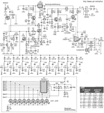
Maybe a 4017 (https://assets.nexperia.com/documents/data-sheet/74HC_HCT4017.pdf) can do it, by providing a voltage on each of its outputs to a trimmer potentiometer (one for each output).
This does not have any oscillator, so it should provide no RF interference.

But it's outputs operate on TTL levels and the maximum VCC is 6v.
Is there any other chip that can provide 8v or more to its outputs?
 

Attachments

  • Ten-Tec_1253_Shortwave_Receiver.gif
    Ten-Tec_1253_Shortwave_Receiver.gif
    73.5 KB · Views: 101
Last edited:

“Electro Mechanical memories” were used on some earlier presettable FM tuners.

Essentially hidden multiturn pots which you could use to set the varactor’s tuning voltage for a particular radio station.

Of course the tuners had AFC circuits to compensate for the inevitable drift.
Even with AFC, sometimes the tuner would require periodic readjustment
 

EEPOTS, last time I used them more than 20 years ago, did have memory, but if I recall properly there was a sequence that had to be applied to store the last wiper position.
 

IC solution is fine as long as it does not have any kind of oscillator (it is to be used very close to an RF circuit)

You mean these multi-turn potentiometers used on TV channels right? Hm...maybe the simplest idea is to have many pots and a way to switch between them, just like in the old TVs...

What is an EEPOT? these IC variable potentiometers? These do not have memories.
--- Updated ---


The resolution should be something like 256 steps in 0-5v, if not a completely analogue (step-free) circuit is to be used. I am not sure I understand what do you mean by the time span?
--- Updated ---

Maybe a 4017 (https://assets.nexperia.com/documents/data-sheet/74HC_HCT4017.pdf) can do it, by providing a voltage on each of its outputs to a trimmer potentiometer (one for each output).
This does not have any oscillator, so it should provide no RF interference.

But it's outputs operate on TTL levels and the maximum VCC is 6v.
Is there any other chip that can provide 8v or more to its outputs?

Time span referring to how long between updates of voltage, worst case longest time
between updates/saves and read of voltage.

Thinking in terms of sample and hold circuit using a cap, again this depends on how often
you store the voltage to be saved.

Note this is a natural for something like ATTINY85, 8 pin micro, can be put to sleep
for low power operation, also reduce internal clock speed to reduce power and emi.
A/D is 10 bits, internal Vref. 4 channel mux if you wanted to do a cal routine or monitor
other stuff. Bypassing to suppress RF, because it draws very little current when operating
easy to do. Onchip EEPROM to store V value. Trigger to capture voltage, use PWM as D/A
to regenerate stored V, just shut it off after you do a read....., only external components RC
for PWM and a bypass cap......

1619465959736.png


Regards, Dana.
 

    neazoi

    Points: 2
    Helpful Answer Positive Rating
Time span referring to how long between updates of voltage, worst case longest time
between updates/saves and read of voltage.

Thinking in terms of sample and hold circuit using a cap, again this depends on how often
you store the voltage to be saved.

Note this is a natural for something like ATTINY85, 8 pin micro, can be put to sleep
for low power operation, also reduce internal clock speed to reduce power and emi.
A/D is 10 bits, internal Vref. 4 channel mux if you wanted to do a cal routine or monitor
other stuff. Bypassing to suppress RF, because it draws very little current when operating
easy to do. Onchip EEPROM to store V value. Trigger to capture voltage, use PWM as D/A
to regenerate stored V, just shut it off after you do a read....., only external components RC
for PWM and a bypass cap......

View attachment 169072

Regards, Dana.
It sounds pro and way easier but too complicated for me unfortunately... :(
On the other hand a simple mechanical selector, using one trimmer potentiometer in each of it's outputs is the easiest thing I can think of, but these pots need to be accessible in a panel design for example for presetting by the user. So it is no longer a case of "reading a voltage" but pre-setting a voltage.
 

Lets take another step back - what are you trying to achieve?
There may be a better way than the one you are trying to implement.
Susan
 

Well it is a memory, indefinitely?
You can't store an analog voltage indefinitely.
There is always some tiny leakage that will change its value.
To store it indefinitely, you will need to convert it to a digital value and store it in some type of digital memory.
 

Here is one approach using an Arduino Nano board and gui programming.

1619475042003.png


Basically two pots are connected to two analog pins, and two PB switches to two pins. When a user sets the V,
then the chan pot V is read and its value written to PWM. Externally you need a RC filter on PWM pin to convert
that to a V which is the saved V.

The blocks are your program, mBlock then converts that to Arduino code and programs the board for you to debug
or as final solution for the boards program.

mBlock 5 is free, Nano board $ 2 - $ 3, you need 4 Rs, 2 for switch pullups, 2 for the RC PWM filter, and 2 caps for the
PWM filter.

The range of output V is 0 to 5V, for a pot ranging 0 - 5 V. Note the PWM output filter needs to go to a Hi Z load, or
you would use an OpAmp as follower to buffer it.

1619475452901.png


Above is Nano board. You use it for development, and then just use the processor on it
for design if you do not want to use the board.

Note the program could be adapted for the ATTINY85 8 pin DIP part, programming the part just
a little more involved (takes another arduino board to program it).

Question, do you need to see the V you are setting on an LCD ? On a display ?


Regards, Dana.
--- Updated ---

For future reference here is another approach as you develop your skills as experience
happens. This is a SOC (System on Chip). Here we get all kinds of digital facilities and
analog. Even the pullup Rs for the push buttons on chip.

What makes this more capable is there is more precision in the analog case, the pots are
fed by a precision internal Vref, and the A/D is more precise at 12 bits. The DACs are real
DACs, in this case current DACs, and their output is sent to a R to convert DAC to a V DAC,
and then buffered thru onchip OpAmps. No PWM filter needed. So your circuit attached
to the voltage you are developing and saving is not compromised in loading.

It also has the faculties to mange a LCD display so you can see what your pots are actually generating
for the V to be saved.

Programming is done in C, this example I think 30 lines of code would suffice.

Board cost ~ $ 15, tools and compiler free.

As you can see many more resources available for use, see right hand window resources used/left.
Counters, timers, basic logic, COM......

1619478523348.png


Lots of fun, you drag and drop out of chip catalog resources, then wire the stuff up onboard, bring out to pins,
also drag and drop, and use the API libraries to run the various resources, eg. you don't write a lot of code per se.


Regards, Dana.
 
Last edited:

    neazoi

    Points: 2
    Helpful Answer Positive Rating
Lets take another step back - what are you trying to achieve?
There may be a better way than the one you are trying to implement.
Susan
I am trying to set the voltages on a varicap and an electronic attenuator (BJT-based). The 2 voltages will drive these elements so they behave in a certain manner on an RF circuit.
Now this is a circuit that is adjustable by the user very often, (the varicap voltage together with the attenuator voltage), on every band change.
So I was thinking of have a "memory" mechanism to make life easier to the user so that he does not have to adjust it every time.

At the beginning I was thinking of a read and store voltage mechanism but afterwards a nice idea came to mind by the answers in this thread, to have the user pre-set the memories (using discrete potentiometers for each) and then having a selector switch to switch the voltages to the appropriate potentiometers. Just like the station memories in the old tube radios (although these were LC-based). That would work and it will have zero RF leakage (as is probably the case with an MCU, although Dana mentioned a thing about low power of the MCU) and it would also solve the higher voltage needed for the varicap compared to that of an mcu output voltage level range, without further circuits. Thankfully since I need only to set 2 voltages, a stereo selector could be used. But this is only practical for just a few memories, not lot.

So I wonder if there is a way to get this idea done preferably without an mcu due to my current lack of programming skills on it, but also considering the RF leakage.
 

Sounds like you need to remember V's specific to each band ? The truly simple
effective way of doing this, accurately and repeatedly, is a MCU or a lot of programmable
logic and a memory element, dac, Vref.....a lot of parts.....

MCU.....hook up with a friend that can program, or start looking at videos on MCU
programming. If you know how to use a 4 function calculator you have been programming
for decades. mBlock is used now by youngsters to program robots. Many videos on this.

I advocate mBlock, or any of the other GUI programmers, like scratch for arduino, flowcode,
ardublock, visuino.... as a starting point. You learn one you can jump to others because they
are so similar. Note if you did Basic language in school there are some options to do this
with Arduinos.

Start simple, make a LED flash, change its flash rate, then make it turn on with a key press.
Build one step at a time.

Costs are cheap, a USB cable, and board, Nano or UNO more than enough.

Regards, Dana.
I can program (web). It is just that I have never spent time in MCU programming. I am going to look at mBlock or scratch for arduino, maybe it is an easy start for easy things that I want to do. I think that I will have to have the platforms to program these, but anyway.
The other option is this one **broken link removed** if one wants to do it PC-free and without any MCU programmers in the loop. This can boot to a single basic program and LCD displays can be connected (there are libraries), so it can be used for the purpose.
I just thought it is a bit too overkill to use this powerful mcu for just reading/storing voltages and put them back, plus there is no DA converter there, plus the interference issue, which is really important in this particular application (which actually tries to eliminate QRM, not produce it)
--- Updated ---

I can program (web). It is just that I have never spent time in MCU programming. I am going to look at mBlock or scratch for arduino, maybe it is an easy start for easy things that I want to do. I think that I will have to have the platforms to program these, but anyway.
The other option is this one **broken link removed** if one wants to do it PC-free and without any MCU programmers in the loop. This can boot to a single basic program and LCD displays can be connected (there are libraries), so it can be used for the purpose.
I just thought it is a bit too overkill to use this powerful mcu for just reading/storing voltages and put them back, plus there is no DA converter there, plus the interference issue, which is really important in this particular application (which actually tries to eliminate QRM, not produce it)
BTW, I have not found how on mBlock I can create arduino code it just creates python...
 
Last edited:

mBlock creates Arduino C or Python.

1619571562021.png


Note there is Tiny Basic available for Atmel AVR and ARM.


Regards, Dana.
 

Status
Not open for further replies.

Similar threads

Part and Inventory Search

Welcome to EDABoard.com

Sponsor

Back
Top