Continue to Site

Welcome to EDAboard.com

Welcome to our site! EDAboard.com is an international Electronics Discussion Forum focused on EDA software, circuits, schematics, books, theory, papers, asic, pld, 8051, DSP, Network, RF, Analog Design, PCB, Service Manuals... and a whole lot more! To participate you need to register. Registration is free. Click here to register now.

Analogue Active Noise Cancellation Headphones

Status
Not open for further replies.

fadverd

Junior Member level 3
Joined
Apr 22, 2013
Messages
28
Helped
0
Reputation
0
Reaction score
0
Trophy points
1,281
Activity points
1,529
hi friends
i am doing final year project of design of active noise cancellation headphones.. i have stucked at point.. and does't find solution. and too worried cause of limited time ahead..:-( so plzz any body can help me.. i ll be much thank full
regards
Fleming
 

thanx dear for your reply..

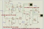
i have simulated this circuit in Proteous software.. but i have't got the required results.. don't where is problem :(
can you help me :)
thanx
 

fgh.jpg
here is the circuit..
its all to all same as you gave me reference in your 1st post..
even i am not getting inverted signal after inverting stage..
i am really too worried cause of lack of time.. :-(
waiting for your kind reply
 

If I have the right impression, you:
(1) put a mic OUTSIDE the headphone,
(2) amplify the signal while also inverting it, and
(3) play the sound INSIDE the headphone.
(4) You adjust its volume to be equal to the ambient noise which penetrates the headphone. The two waveforms cancel.

Your schematic is made up of several sub-circuits. While you are still developing the project, you need to test one stage and make sure it is working, rather than expect all stages to work properly right away.

So I would not try to mix the music with the noise-cancellation yet. You must first get a proper signal from each op amp one at a time.
 
thanx for your kind attention..
i am getting amplified signal from first stage but not getting inverted signal from 2nd stage.. although my 2nd stage is just according to schematic of INVERTING OP AMP.. But still i am not getting output.. :(
waiting for your kind reply :)
 
Last edited:

When one stage works and the next one does not, you must start troubleshooting.

Try sending a variety of signal levels into the 2nd stage. Find out if anything will get a result. What level of input will cause a change in output.

Looking at your schematic...
You have op amps which are on a single supply. Since you are amplifying audio (AC) signals, you need to give the op amps a bipolar supply.

- - - Updated - - -

When one stage works and the next one does not, you must start troubleshooting.

Try sending a variety of signal levels into the 2nd stage. Find out if anything will get a result. What level of input will cause a change in output.

Looking at your schematic...
You have op amps which are on a single supply. Since you are amplifying audio (AC) signals, you need to give the op amps a bipolar supply.
 
  • Like
Reactions: fadverd

    fadverd

    Points: 2
    Helpful Answer Positive Rating
    V

    Points: 2
    Helpful Answer Positive Rating
Really sorry for replying you late...as said by BradtheRad...start making the circuit stage by stage.

To invert the sound coming in from the outside, you use the basic "Inverting Amplifier." Using the formula for it (Vo=((R1+R2)/R1)*Vin) and testing in varied environments, figure out the needed values of the resistors. (Depending on the mic you use, you may need some additional circuitry before the input to the op amp).

Or you can try out this **broken link removed**
 
  • Like
Reactions: fadverd

    V

    Points: 2
    Helpful Answer Positive Rating

    fadverd

    Points: 2
    Helpful Answer Positive Rating
I has known that opamp (Cmos Technology) overcome some ideal limited of opamp(Bipolar), Now many Technology such as GaAs has instead but in the future I think nano technology that not depend on type of materail will overwhelm market because low power technology be needed.
 
hello !
have a good day !
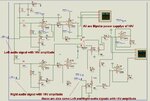
i have simulated circuit again stage by stage as you said.. this time i have got desired and expected output signals after 1st (amplifying stage) and 2nd stage(inverting stageoverall complete circuit.JPGresult after inverteing stage... as expected...jpgresults after summing stage.. not expected.JPG that results i have attached along..
but unfortunately i have not got desired and expected signal outputs after 3rd stage(summing stage). i have attached the final output signals (picture) and overall complete circuit .
please have a look.. and help me.. :)
i ll be waiting for your kind reply..
Regards
Fleming

- - - Updated - - -

overall complete circuit.JPGresult after inverteing stage... as expected...jpgresults after summing stage.. not expected.JPG
hello !
have a good day !
i have simulated circuit again stage by stage as you said.. this time i have got desired and expected output signals after 1st (amplifying stage) and 2nd stage(inverting stage) that results i have attached along..
but unfortunately i have not got desired and expected signal outputs after 3rd stage(summing stage). i have attached the final output signals (picture) and overall complete circuit .
please have a look.. and help me.. :) or you can suggest me alternative solution of this problem
i ll be waiting for your kind reply..
Regards
Fleming
 

Very good, you are making progress.

Evidently it helped to change to bipolar power supplies for the op amps.

It's back to the steps of troubleshooting. You have to work on the 3rd stage op amp by itself, and apply every combination of input signals, to find out how to get the output to change in any way. Change the feedback resistor, supply polarities, etc. It's all anyone can do.
 
Read "Design of Analog integrated Circuit and System" by Kenneth R.Laker/Willey M.C.Sansen
 
i have made several attempts but all in vain.. even i have changed op amp but could't find result.. you suggest some thing

- - - Updated - - -

i have made several attempts but all in vain.. even i have changed op amp but could't find result.. you suggest some thing

- - - Updated - - -

from where i take this book?? please send me link
 

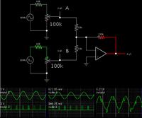
This should be a duplicate of the last stage of your layout.


This simulator (www.falstad.com/circuit) does not show supply leads. It only has a setting for output V min and max. The output occupies the same range as if supply leads were shown.

I wonder about your supply V settings at the third op amp.

Did you try various high and low input levels? At both potentiometers?

Something should have worked. You should have seen some signal from the output.

- - - Updated - - -

This should be a duplicate of the last stage of your layout.


This simulator (www.falstad.com/circuit) does not show supply leads. It only has a setting for output V min and max. The output occupies the same range as if supply leads were shown.

I wonder about your supply V settings at the third op amp.

Did you try various high and low input levels? At both potentiometers?

Something should have worked. You should have seen some signal from the output.
 
I think this is the equivalent circuit and not optimize yet although elabolated spice model apply. Try to engineering before use the circuit preferly and perfect soon.
 
hello have a good day.. !
i have simulated this circuit.. now its working very nice and just according to expectations..
yahoooooooooo :)
thanx for your kind attention.. :) :)
now i am implementing its hardware..
i will contact you if i have any query..
 

thats good to hear from you...keep it up
 
hello !
i am implementing above mentioned circuit on breadboard.. i have query.. how can i give audio signal as a input to microphone??
that audio signal is a recorded signal in my lap top..
Regards
Fleming
 

Status
Not open for further replies.

Part and Inventory Search

Welcome to EDABoard.com

Sponsor

Back
Top