Continue to Site

Welcome to EDAboard.com

Welcome to our site! EDAboard.com is an international Electronics Discussion Forum focused on EDA software, circuits, schematics, books, theory, papers, asic, pld, 8051, DSP, Network, RF, Analog Design, PCB, Service Manuals... and a whole lot more! To participate you need to register. Registration is free. Click here to register now.

Ampop subtractor operational OPAMP amplifier subtractor circuit help

Status
Not open for further replies.

vitoa

Member level 2
Joined
Jul 28, 2015
Messages
52
Helped
4
Reputation
8
Reaction score
4
Trophy points
8
Activity points
522
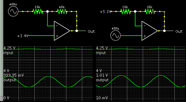
Hi, I need to built a circuit to subtract a reference voltage of 4V from a variable signal from 4 to 4,25V
This interval 250mV must be amplified 4 times. I need output variable from 0 to 1V
Can someone help me designing this circuit and resistor values Any one knows a low power ampop single supply operating from 2,8V to 5V?

subtractor.jpg

Any help is welcome
 
Last edited:

It's possible to do this all-in-one with an op amp...
If you apply the correct reference voltage, and the correct gain.

It isn't easy to solve by formula. I cheated and used a simulator.

Notice your schematic (left) requires Vref=3.4, gain=4. It inverts the phase of your incoming signal.


The alternate method (right) requires Vref=5.3, gain=3. It does not invert the phase of your incoming signal.
You may not have access to 5.3V. Then consider putting a diodes/zener/led in series with your incoming signal. This drops a volt or two. It allows you to use a Vref of 2 or 3 or 4V.
 

This may work, but you will have some unwanted distortion occurring near the 0V output swing. To eliminate this you need to run some small negative rail on the op-amp supply. It depends if this distortion is important to you. If you use the signal just to drive some level meter or something, then it is no issue.

The simulator predicts about 4% THD for this setup.
 

Attachments

  • amp1.png
    amp1.png
    23.6 KB · Views: 125

Hi,

Your picture in post#1 is correct.
Per design it subtracts the 4V Ref from your input signal.

The only thing now you need is to set the gain.
0.25 input swing should generate 1.0V output swing. Gain = 1.0V / 0.25 V = 4.

Gain setup for your circuit is: Gain = R2 / R1.
With a gain of 4 this means R2 = 4 × R1.

Now you need to select useful values of R2 and R1.
I'd say for low power operations any value of 10k ... 100k for R1 is good.

Just multiply the chosen value by 4 and get the value for R2.

For example 10k and 40k....or 25k and 100k.

Klaus
 

Thanks a lot for help.
Now just need to choose a low power opamp supply from 2,7V to 5V and low current consumption.
I think OPA170 or LT1006 - Precision, Single Supply Op Amp will do.

Regards

- - - Updated - - -

I need help to choose resistors. Im using a voltage reference IC 2,5V and and variable input from 3V to 2,7V.
So voltage out maximum is 3-2,5 =0,5V * 4gain =2 V 3-2,7V=0,3 * 4 = 1,2V

I want to choose up to 3V output so 0,5*6 gain=3V 1,8V

Is there any voltage reference of 3V or enar 3V?

Need help to choose resistors.
 
Last edited:

Hi,

Is there any voltage reference of 3V or enar 3V?
I just used farnell: more than 2400 voltage reference ICs.
180 pieces with 3V.

Klaus
 

Hi the ideia is this one, need to get porportinal output from AD8307.
AD8307 will output 2,7V to 3V range. Need to use 2.5V referece IC
Voltage divisor is to get output 3V down to 2.5V.
Compare variable voltage to 2.5V .Variable voltage drop 0.5V with resitor divisor.
AD8226 is good choise because one resistor fix gain to 5

IMG_4882.JPG
 

Status
Not open for further replies.

Similar threads

Part and Inventory Search

Welcome to EDABoard.com

Sponsor

Back
Top