Continue to Site

Welcome to EDAboard.com

Welcome to our site! EDAboard.com is an international Electronics Discussion Forum focused on EDA software, circuits, schematics, books, theory, papers, asic, pld, 8051, DSP, Network, RF, Analog Design, PCB, Service Manuals... and a whole lot more! To participate you need to register. Registration is free. Click here to register now.

Amplitude modulation, lower carrier on max audio?

Status
Not open for further replies.

neazoi

Advanced Member level 6
Joined
Jan 5, 2008
Messages
4,123
Helped
13
Reputation
26
Reaction score
15
Trophy points
1,318
Location
Greece
Activity points
36,955
Hi,
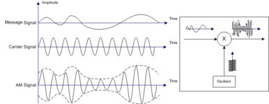
According to wikipedia https://en.wikipedia.org/wiki/File:Illustration_of_Amplitude_Modulation.png when the audio is louder, one should see a higher level carrier on an Amplitude modulated transmitter.

But I have noticed on ham radio gears, that the other way is true.
For example in one of them, the idle carrier was 100W and the peaks when shouting to the microphone were 35W.

Which of the two is true, the carrier is reduced or increased on AM when the AF signal that is modulating it gets louder?
 

Attachments

  • Illustration_of_Amplitude_Modulation.png
    Illustration_of_Amplitude_Modulation.png
    41.1 KB · Views: 129

At high volume the AM carrier needs to make larger excursions.

However at low volume (or idle) there's the question, What is carrier intensity? 50 percent? 100 percent? Your experiment suggests it's more like 100 percent, even though it might seem wasteful to use full power broadcasting silence. I suppose some carrier needs to go out on the airwaves, perhaps as an occasional beacon for aircraft. Or, to provide an indicator on radios which have a readout for strength of AM reception.
It is 100% on idle. excursions are always downwards. I am watching this on a needle-based analogue power meter, not a scope.
 

Hi,

AC input on an AM should always go both ways.. symmetrically.
Since the power is proportional to square of the voltage I expect the RMS of an AM modulated signal higher than on the non modulated carrier.

Simplified: 1V peak carrier, +/- 0.1V modulation... results in 0.9V ... 1.1V modulated signal.
1.1^2 = 1.21
0.9^2 = 0.81
average both: (1.21 + 0.81) / 2 = 1.01 ... this is more than the unmodualted 1.0

I guess: V_RMS_Out = sqrt( V_RMS_carrier ^2 + V_RMS_modulation^2)

Klaus
It doesn't make sense then. The idle carrier was 100W and the peaks when shouting to the microphone were 35W. The power meter needle (showing the average) clearly goes only downwards not upwards.
 

It depends upon how the modulation is superimposed on the carrier. What you are describing is, or was many years ago described as downward modulation. Some forms of grid modulation would give that result, I used it myself back in the early 70's. The resting carrier is full carrier and as the modulation is increased (assuming sine wave) the sine wave would grow from the peak of the carrier towards zero carrier. Easier to draw than explain in words.
 

It depends upon how the modulation is superimposed on the carrier. What you are describing is, or was many years ago described as downward modulation. Some forms of grid modulation would give that result, I used it myself back in the early 70's. The resting carrier is full carrier and as the modulation is increased (assuming sine wave) the sine wave would grow from the peak of the carrier towards zero carrier. Easier to draw than explain in words.
No it's ok I understand this and thank you very much.

Indeed this is AM produced on a Yaesu FT-301, a late 70's rig, which is all solid state (i.e. no tubes in the final). Idle carrier is 100W (max rig power) and at full modulation it goes down to 35-40W.

I have just tested AM modulation on a modern rig, a Kenwood TS-480HX and it is the other way round!
The idle carrier is allowed to be set only at 50W at maximum by the menu (and not 100W as in the older rig) and when I speak in the microphone, the average output power on the power meter needle goes up, not down like the old rig.

This is something new to me! Upwards and downwards AM modulation.
Now I wonder, won't this matter to the receiver? Why does the detected signal sound ok, shouldn't it sound reversed in volume or/and in frequency (AF) due to the reverse AM modulation scheme?
 

The I suspect there is something wrong with the way the meter measures the power.
I do not think so. I has been tested on many transceivers and also with the newer rig which behaves differently..
It must be downwards AM modulation and I have found a page explaining that. https://www.qsl.net/wa5bxo/asyam/aam3.html It has advantages and disadvantages.
The idle carrier is held at maximum level and the modulation reduces it accordingly.
 

Status
Not open for further replies.

Part and Inventory Search

Welcome to EDABoard.com

Sponsor

Back
Top