poodina
Junior Member level 1
I am in need of help designing a Class A or Class AB amplifier for a frequency range of 100KHz -900Khz. Generated using a microcomputer , level shifted and amplified to be a pure sine wave with origin at zero.
I have a restriction of using +/-24V supply or single 24V.
The main requirement of the amplifier is that the output single has to be at least 48V peak [96Vpp]. This single will be give to a copper coil of single turn.
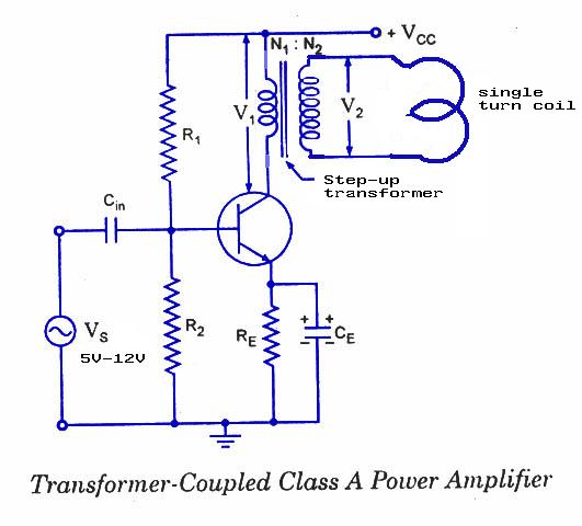
I had a Idea of using a transformer coupled output stage for a class A amplifier to archive the desired output.
Would like know if this approach is correct or is there any other way to achieve the 48volt peak wave, from a single [class A amp] or dual [class AB amp] 24Volt supply.
The Amplifier setup I am thinking of using is in the attachment.

If any other Idea or any other circuit would be appreciated.
I have a restriction of using +/-24V supply or single 24V.
The main requirement of the amplifier is that the output single has to be at least 48V peak [96Vpp]. This single will be give to a copper coil of single turn.
I had a Idea of using a transformer coupled output stage for a class A amplifier to archive the desired output.
Would like know if this approach is correct or is there any other way to achieve the 48volt peak wave, from a single [class A amp] or dual [class AB amp] 24Volt supply.
The Amplifier setup I am thinking of using is in the attachment.
If any other Idea or any other circuit would be appreciated.