uniquadrion
Newbie level 4

- Joined
- Nov 29, 2014
- Messages
- 5
- Helped
- 0
- Reputation
- 0
- Reaction score
- 0
- Trophy points
- 1
- Activity points
- 47
Due to my previous post got deleted somehow, this is my second post.
Hello,
First of all, I have a project that can do;

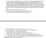
It accomplishes all of this perfectly. However, now I need to edit my program in a way that it multiplies 2 numbers instead of add them (I will take out add function and replace it with multiply instead). I need to do this with arithmetic operator which is * operator, as my instructor required and he claimed that verilog would accept it. However I got stuck on this because my ALU doesnt use + arithmetic operator so its not as easy as changing operator, which contrasted with what he said. Here are some screenshots from my ALU code.


So to make long story short, I need the adder to be a multipler of 2 numbers with the asterisk (*) operator. I was told that it would be very easy due to changing the operator however my ALU code is not written with operators. Otherwise it would have been easier as my instructor mentioned.
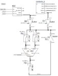
This the circuit of my project;

and for more detail, here I attached my project.
View attachment CPU.zip
Let me know if you have a question about it.
Thanks!
Hello,
First of all, I have a project that can do;

It accomplishes all of this perfectly. However, now I need to edit my program in a way that it multiplies 2 numbers instead of add them (I will take out add function and replace it with multiply instead). I need to do this with arithmetic operator which is * operator, as my instructor required and he claimed that verilog would accept it. However I got stuck on this because my ALU doesnt use + arithmetic operator so its not as easy as changing operator, which contrasted with what he said. Here are some screenshots from my ALU code.

So to make long story short, I need the adder to be a multipler of 2 numbers with the asterisk (*) operator. I was told that it would be very easy due to changing the operator however my ALU code is not written with operators. Otherwise it would have been easier as my instructor mentioned.
This the circuit of my project;

and for more detail, here I attached my project.
View attachment CPU.zip
Let me know if you have a question about it.
Thanks!
