Continue to Site

Welcome to EDAboard.com

Welcome to our site! EDAboard.com is an international Electronics Discussion Forum focused on EDA software, circuits, schematics, books, theory, papers, asic, pld, 8051, DSP, Network, RF, Analog Design, PCB, Service Manuals... and a whole lot more! To participate you need to register. Registration is free. Click here to register now.

[SOLVED] Altium: Can anyone view STEP PCB3D models in "live" 3D PCB editor mode?

Status
Not open for further replies.

jpeskin

Newbie level 5
Joined
Apr 20, 2012
Messages
10
Helped
0
Reputation
0
Reaction score
0
Trophy points
1,281
Activity points
1,399
3D viewing mode seems to mostly work, but it only renders parts that were created using the built-in "3D bodies" feature of Altium. When I import STEP files, they don't show up in 3D mode. However, when I use Legacy 3D mode, the STEP models appear just fine there. I have checked all preferences in the PCB editor to prefer STEP

It's basically the same exact problem reported here:
https://www.edaboard.com/threads/221753/

This is Altium 10.589

Amusingly, if I export the Legacy 3D view and import it into the PCB Editor (Place... 3D Body..), it renders just fine.

Is anyone else able to view imported STEP models in the interactive 3D view?

Thanks
 

Hi

Do you have the direct X option enabled? Make sure you have 3D bodies turned on in the preferences. It's also under PCB Editor - Display.
Is the standoff height correct. Maybe the part is under the pcb and does not show.
 

lebronic

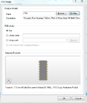
could you upload the footprint for the DIP-16. It seems the 3d body has the wrong orientation.
 

Ashampoo_Snap_2012.04.20_18h49m36s_005_.png

this is it
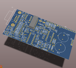
the problem is when i try to print out the pcb it prints with the CD4053 in the toplayer !!
 

have you tried and updating the footprint from the libraries, just to make sure everything is OK?
 

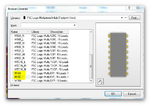
i tried both of these model shown in the pic
but i got the same thing in PCB
Ashampoo_Snap_2012.04.20_18h58m47s_006_.png
and when i view in 3D its shown in the wrong orientation
 

Here you are
 

Attachments

  • SPO2_AMP_Circuit.rar
    457.6 KB · Views: 102

did you use Legacy 3D view ?
 

No, I use the direct X setup. Don't have any of the Altium libraries installed. The footprints also do not have any model attached to them.
Maybe that's why mine looks different.
 

but on the print out you will still see the IC being printed with the top layer traces
how to get rid of it there
 

Hi

Do you have the direct X option enabled? Make sure you have 3D bodies turned on in the preferences. It's also under PCB Editor - Display.
Is the standoff height correct. Maybe the part is under the pcb and does not show.

Thanks for the thoughts.

Yes, I have direct X enabled and both "Show Simple 3D Bodies" and "Show STEP Models" selected under PCB Editor - Display. Also, in the 3D View config I have "Prefer STEP in components" selected. The part is not under the PCB because it appears in the proper place when I export a Legacy 3D View.
 

Try this.

create a PCB library from the PCB and then in the library editor verify if the 3D body is there.
you can switch between 2D and 3D by using the shortcut keys 2 and 3.
 
Try this.

create a PCB library from the PCB and then in the library editor verify if the 3D body is there.
you can switch between 2D and 3D by using the shortcut keys 2 and 3.

AHA! I think you have helped me identify the source of the problem! I have always been working off a self-made Integrated Library that consists of three files:
.SchLib, .PcbLib, .PCB3DLib

Many parts in this IntLib (now called LibPkg?) were created back with Altium 6.X. At this time, the method of linking in STEP models was to import them into the .PCB3DLib file and then link that model to your part by adding it to the SchLib part ("Add Footprint... PCB3D"). Or at least that was the method that I used back then, and it worked. Presently, when I select these older parts under SCH Library panel, it shows that both the 2D footprint from PcbLib and the 3D model from PCB3DLib are attached to the .SchLib part. But when I add these parts to a schematic (and update the related PCB), the 3D STEP model never shows up (unless I do a Legacy 3D View). However, when I'm editing the part's footprint in PcbLib, I of course see nothing when I press '3', because there is no 3D body inside this 2D footprint.

NOW... if I take the approach you alluded to above, and I stop using PCB3DLib for my STEP models, and instead import the 3D STEP model directly into the 2D Footprint that is in PcbLib (by "Place... 3D Body"), then I can quite easily switch between '2' and '3' in the library editor. And furthermore, when I create a new SchLib part and add the 2D/3D "footprint" from the .PcbLib, then the 3D model appears in the 3D view when I place this part into new PCB projects!

So problem solved--thanks! I guess I just didn't realize that the new workflow is that you embed your step model directly in the 2D footprint. Or maybe that's always been the workflow and I didn't know the proper method. At this point, I really don't know what the purpose of having a separate PCB3DLib file inside a LibPkg would be?? I guess it's just there for legacy support??

Thanks!
 

I think Altium switched with Version 9 to having 3D models directly imported into the footprint. And no longer use outside 3d libraries.
 

Status
Not open for further replies.

Part and Inventory Search

Welcome to EDABoard.com

Sponsor

Back
Top