nguyenvanthien
Member level 4
Hello everybody,
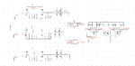
I have an idea about aligning rising edge pulse as below picture. My purpose is distance phase between ck8 and ck1 equal ck1 and ck2. So, I use phase detector (PD) to detect them and take to Charge Pump. Then, control voltage return to contrl delay ck8.
As you can see, I fix ck1 and ck2, I set distance phase between ck8 and ck1 is 250p, distance phase between ck1 and ck2 is 260p. But, in locked state, distance phase ck8- ck1 only 251p (not 260p as I expect). The control voltage didn't change enough to control out8.
So, where's the wrong in my circuit? How can I fix it?
Thanks!