aistruckz
Newbie level 4

- Joined
- Feb 14, 2013
- Messages
- 5
- Helped
- 0
- Reputation
- 0
- Reaction score
- 0
- Trophy points
- 1,281
- Activity points
- 1,314
hello,
im a student of computer engineering and im on my final year which we do have and implementation of our proposed project...it is entitled ALCOHOL DETECTION SYSTEM FOR CARS WITH GPS TRACKER..
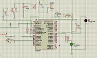
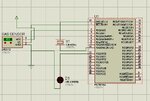
my problem is on its schematic..please help me about the schematic diagram from the sensor to the pic18f452 or pic18f4620...
the process is this,when the driver is detected drunk using the mq2 gas alcohol sensor it will buzz which indicates a drunk driver then it will send an sms notification to the gps tracker..
in connection with this..i only need the schematic from the sensor,buzzer to the pic then to the cellphone...hope u'll help me about this...thank u very much:razz:


