Continue to Site

Welcome to EDAboard.com

Welcome to our site! EDAboard.com is an international Electronics Discussion Forum focused on EDA software, circuits, schematics, books, theory, papers, asic, pld, 8051, DSP, Network, RF, Analog Design, PCB, Service Manuals... and a whole lot more! To participate you need to register. Registration is free. Click here to register now.

After stable Voltage output my MOSFET drain and high side of half bridge is in bursting mode

Vikas ji

Newbie
Joined
Apr 9, 2024
Messages
4
Helped
0
Reputation
0
Reaction score
0
Trophy points
1
Activity points
27
Hello everyone I am new here.
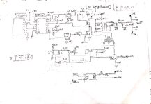
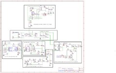
I have problem in half bridge SMPS in which my output voltage is 23v stable which I set through optocoupler feedback. But after output voltage stable when input given around 120 v AC the drain and High side gate goes in bursting mode and not making own smooth.

I just want to know in half bridge SMPS is normal or it is a problem.

Dummy load is 100k and pwm frequency 50khz,
Deadtime 900ns,
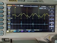
The drain waveform and I have is
 

Attachments

  • New Doc 04-09-2024 11.17.jpg
    New Doc 04-09-2024 11.17.jpg
    394.7 KB · Views: 78
  • IMG20240406113810.jpg
    IMG20240406113810.jpg
    3.4 MB · Views: 75
Thanks for your reply.
It is only test purpose before I connect MOSFET with it. It is used to discharge high side so I can get pulse in CRO.
Then after that everything ok on this predriver module I removed this 1k resistor and connect the MOSFET and so on circuit.
SMPS circuit working fine .
But when I check the drain point it shows this type of waveform like sine wave not own it is ok or not
 
The converter is running with effectively no load, resulting in low duty cycle. Without knowing the transformer properties, it's hard to say if the waveforms are o.k.
 
I make the pwm stable by using 48v zener diode. So the output is approx 50v and pi filter capacitor at output is 1000uf. But after stable voltage current rising slowly without load and watt also increasing.
 
..From scm in top post, it looks like you have 1000uF just downstream of the output diodes...that should not be there.
 
you have put a dummy load on the converter ( the zener ) to " stabilize it "

actually at no load - your previous condition - one expects the control to bounce around a bit - as when power goes to the output it is stored as a higher than target Vout on the cap, and it takes a while for it to bleed down to where the control ckt starts the pwm again . . .
--- Updated ---

@cupoftea - it has a soft start - but you have spotted exactly why these types of designs fail after a variably short period in the field - even with soft start.

on the plus side - he has removed the need for output snubbers on the diodes ( ha ha )
 

LaTeX Commands Quick-Menu:

Part and Inventory Search

Welcome to EDABoard.com

Sponsor

Back
Top