Continue to Site

Welcome to EDAboard.com

Welcome to our site! EDAboard.com is an international Electronics Discussion Forum focused on EDA software, circuits, schematics, books, theory, papers, asic, pld, 8051, DSP, Network, RF, Analog Design, PCB, Service Manuals... and a whole lot more! To participate you need to register. Registration is free. Click here to register now.

Advise on current mode control for SMPS

Status
Not open for further replies.

jegandren

Junior Member level 3
Joined
Dec 13, 2007
Messages
31
Helped
1
Reputation
2
Reaction score
0
Trophy points
1,286
Activity points
1,502


Hi all,

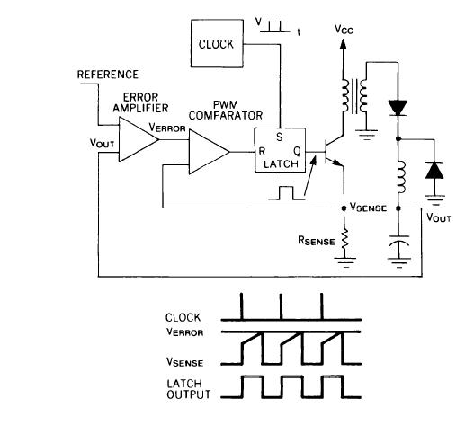
im trying to design the current mode controller in matlab/simulink. but i have a problem in comparing the error voltage to the sense current. can any one please advise on this or it would be great if you could share your idea.
thanks
 

It looks like a forward converter without reset wiring. Please check your schematic. For your question, the voltage loop may need compensation; at mean while, your current loop may or may not need a compensation slope for current loop stability. Look up the current mode control material or text book. Couple links for your reference

**broken link removed**
http://www.venable.biz/tp-05.pdf
 

That is pretty much your standard current mode loop. As was already stated, your error amp is probably going to need compensation. Also, depending on your duty cycle you may need to add slope compensation. I don't understand what your question is regarding comparing the error amp output to the current sense signal. That is done with a simple comparator.
 

For D>50%, you need the slope compensation sheme where D is Vo/Vin


hi all,

thanks a lot for your guidence. Now i have able to track the control voltage with the sensed inductor current. But now i have a problem in the error voltage part. for instance when the converter has a load of 100W the output voltage is 25 V but when there is a step of load to 150 W the output voltage drops to 23v and does not increase back to 25 V. It sticks to 23 V and when i increase the load to 200 W the output voltage becomes 20V. need advise on this matter.
 

It sounds like you are bumping into current limit. Hence you can't supply enough current to support the voltage. Is your error amp output at its maximum high voltage? Can it go any higher? If it is then you are definitely hitting current limit and need to either reduce your current sense ramp or increase the high range of your error amp.
 

Status
Not open for further replies.

Similar threads

Part and Inventory Search

Welcome to EDABoard.com

Sponsor

Back
Top