Continue to Site

Welcome to EDAboard.com

Welcome to our site! EDAboard.com is an international Electronics Discussion Forum focused on EDA software, circuits, schematics, books, theory, papers, asic, pld, 8051, DSP, Network, RF, Analog Design, PCB, Service Manuals... and a whole lot more! To participate you need to register. Registration is free. Click here to register now.

Advice request - Boost or multiplier ?

Status
Not open for further replies.

gag2000

Member level 5
Joined
Dec 4, 2009
Messages
91
Helped
20
Reputation
40
Reaction score
20
Trophy points
1,298
Location
Fr
Activity points
1,836
Dear all,

I am new to power electronics (but quite experienced in digital and analog design).
At the moment, I am trying to design an inverter. Thus, I need a DC supply of about 400V and able to deliver 2kW.
I would like to avoid transformer because of the size and weight wrt power needed...
After few readings, I have two solutions :
- a PFC with a boost circuit ;
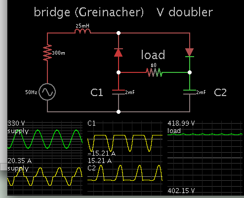
- a voltage multiplier with capacitors and diodes.

Which one would be the best topology, and why ? Is there any other solutions ?

Thank you for your advice/help.
 
Last edited by a moderator:

Re: Advice request - Boost or multilier ?

The boost PFC is the standard solution for such high power levels. Never heard of one based on voltage multipliers. No regulation, very poor PF, huge component size, etc...
 
The CR-C multiplier will be expensive and unreliable with Caps that can handle loads of ripple current.

The peak current will be inverse to the allowed ripple, such as 10x at 10% ripple even if just at 10% duty factor. The Cap ripple current may be rated at 110'C with the rated RMS current * ESR thus require very large Caps($)

The other factor is the EMI and THD & poor PF you are injecting into the line.

First define all requirements; budget; time ; surge; output load regulation, ripple, THD , inrush, input regulation 3kV or 6kV insulation?
Load response? Source impedance? Load impedance? MTBF?

It may end up being a make or buy decision.

It may be you have an EDM solution in mind, which demands much more in current and voltage sensing for regulation.

Always research specs and make one before starting any design.

**broken link removed**
 
For theoretical comparison (and because I like to watch simulators running), here is a voltage doubler which converts 230VAC to 400VDC at 2 kW.


The high Ampere levels may make it impractical.

The inductor has two purposes: (a) by limiting current flow it is a means to adjust output voltage, (b) it reduces the intensity of spikey behavior that would otherwise occur.

The capacitors each need to endure 200V.

There is also the Villard type of voltage doubler. The output capacitor would need to endure 400 V.
 
Thank you all for your answer.
It will be a very low production (few models, perhaps few tens). The cost is not the point.
Main point is reliability.

I will have further reading on PFC+boost and try to simulate it.
Also the PFC is a good point for the whole inverter.

Regards,
RG
 

Status
Not open for further replies.

Similar threads

Part and Inventory Search

Welcome to EDABoard.com

Sponsor

Back
Top