ravi_karthik
Newbie level 3
adc0804 & 0808 readings going 0 after half the total voltage read through i/p channel
Can someone explain why this strange behaviour is seen while interfacing adc0808 or adc0804 with at89s52 microcontroller.
Iam trying to read 5v connected to channel 0 of adc0808 , hence it should give 255 when i read 5v and 0 when i read 0v.
But strangely it gives the correct readings upto 127 that is 2.5 v but after that it goes down to 000 then 001 and then again some readings in between
are correct upto 255 that is 5v.
Same strange behaviour is seen when adc0804 is interfaced with at89s52.
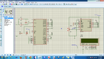
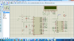
In proteus simulation the the code below(adc0804) and the attached adc0808 works but in hardware the above behaviour is reflected.Reference schematics are provided .Please let me know if any one need any further details regarding the same.
Vref in adc0808 is connected to 4.95v and vcc is 4.95v ...
in adc0804 vref/2 is left unconnected.
Can someone explain why this strange behaviour is seen while interfacing adc0808 or adc0804 with at89s52 microcontroller.
Iam trying to read 5v connected to channel 0 of adc0808 , hence it should give 255 when i read 5v and 0 when i read 0v.
But strangely it gives the correct readings upto 127 that is 2.5 v but after that it goes down to 000 then 001 and then again some readings in between
are correct upto 255 that is 5v.
Same strange behaviour is seen when adc0804 is interfaced with at89s52.
In proteus simulation the the code below(adc0804) and the attached adc0808 works but in hardware the above behaviour is reflected.Reference schematics are provided .Please let me know if any one need any further details regarding the same.
Vref in adc0808 is connected to 4.95v and vcc is 4.95v ...
in adc0804 vref/2 is left unconnected.
Code:
//ADC0804 CODE

#include<at89x52.h>		//----Including the Reg file

//------------Assigning Control bits for LCD control---------/
sbit rs = P3^0;	//----Pin0 of port3 is defined as rs pin for lcd control using this command—
sbit rw = P3^1;//----Pin1 of port3 is defined as rw pin for lcd control using this command-lcd control using this command---
sbit en = P3^2;//----Pin2 of port3 is defined as en pin for

sbit cs = P2^5;
sbit rd = P2^6; //----Read function for enabling ADC read----//
sbit wr = P2^7;//----Write Function for writing into ADC----//
sbit intr = P2^0;//----Interrupt Function which indicates the End of Conversion----//
//----------------------------------------------------------//

//------------Proto-type Decleration-----------------//
void init_lcd();		//-----Function used for Initializing LCD ------
void lcd_comm(unsigned char value1); //------Function used to send command using pass by reference type-----
void lcd_data(unsigned char value2);	//------Function used to send data using pass by reference type-----
void lcd_msg(unsigned char *ch); //----Sending a String uisng pass by pointer method------
void delay(unsigned int ms);	//------Function use to generate 1ms delay-------

//-----Defining the ADC Function-----//
void adc_init();
//-----Inializing  adc -----//
void adc_read();
//----Reading Data from ADC---//
void Converter(unsigned char v4);//----Converter data to ascii for display in LCD---//
//---------------------------------------------------//

unsigned char ascii_lut[] = "0123456789ABCDEF";

//-------------Main Program-------------------------//
void main()
{
/
	init_lcd();			//-----Initializing LCD
	adc_init();			//-----ADC initialize
	lcd_comm(0x80);	//-----1st line of LCD
	lcd_msg("VOLTAGE = ");//----Send a String
	while(1)
  {
	       adc_read();	//-- ADC data is send to mu and displayed in LCD
	}
}


void adc_init()
{
	cs = 0;
	wr = 1;				//------Initialize the write signal as high
	rd = 1;				//------Initialize the read signal as high
	intr = 1;			//------Interrupt Pin to show end the Conversion
}

void adc_read()
{
  unsigned char v;
	cs = 0;
	wr = 0;		//----When Write Signal goes high to low to high
	wr = 1;		//----It state End of Conversion
	while(intr == 1); //----Wait till end of conversion
	rd = 0;		//---Read is enable to read data from it
	v = P0;		//----Move data of ADC to variable v
	Converter(v);
	intr = 0; //---Clearinng for next state
}

void Converter(unsigned char v4)
{
 //---Converter to analog input voltage
	float g,h;
	unsigned int d,t;
	g = ((v4 * 5)/255);	//--Analog input voltage is float type---/
	d = g;			//--Move float into interger will eliminate the decimal point---//
	h = g - d;		//--Now calculate the difference between float and interger
	t = h * 100;		//--Now Removing the decimal point//
	lcd_comm(0x89);	//---Forcing to the Centre
	lcd_data(d|(0x30));
	lcd_data('.');
	lcd_data(((t/10)%10)|(0x30));
	lcd_data(((t)%10)|(0x30));
	lcd_data('V');

//---Converting ADC data to Decimal

	lcd_comm(0xC0);
	lcd_msg("D=");
	lcd_data(((v4/100)%10)|(0x30));
	lcd_data(((v4/10)%10)|(0x30));
	lcd_data(((v4)%10)|(0x30));

//----Converting the data to hexa

	lcd_comm(0xC7);
	lcd_msg("H=");
	lcd_data(ascii_lut[((v4 & 0xF0)>>4)]);
	lcd_data(ascii_lut[((v4 & 0x0F))]);
}

void init_lcd()
{
	lcd_comm(0x38);		//----Initializing 16x2 line LCD dispaly
	delay(10) ;				//-----10ms delay
	lcd_comm(0x0E);		//----Setting Display ON and Cursor as Blinking
	delay(10);				//-----10ms delay
	lcd_comm(0x01);		//-----Clearing the LCD display
	delay(10);				//-----10ms delay
	lcd_comm(0x06);		//-----Auto incrementing Cursor
	delay(10);				//-----10ms delay
	lcd_comm(0x80);		//-----Setting first location on first line of LCD
	delay(10);				//-----10ms delay
}


void lcd_comm(unsigned char value1)
{
	P1 = value1;	//----Sending the command to lcd from Port0
	rs = 0;	//----RS = Register Select pin, when [rs = 0] means its Command register
	rw = 0;	//----RW = Read / Write pin, when [rw = 0] means write function
//----EN = Enable pin, it is use to latch data to lcd when it has high to low pulse at en pin
	en = 1;
	delay(1);	//----1ms delay
	en = 0;
}

void lcd_data(unsigned char value2)
{
	P1 = value2;//----Sending the command to lcd from Port0
	rs = 1;	//----RS = Register Select pin, when [rs = 1] means its Data register
	rw = 0;	//----RW = Read / Write pin, when [rw = 0] means write function
//----EN = Enable pin, it is use to latch data to lcd when it has high to low pulse at en pin
	en = 1;
	delay(1);	//----1ms delay
	en = 0;
}

void lcd_msg(unsigned char *ch)
{
while(*ch != 0)//----Creating super loop with condition that pointer ch pointing data using address is not equal to zero
{
	lcd_data(*ch);	//-----Sending String by pointing addresss of data
	ch++;		//-----Incrementing the ch pointer variable
	}
}

void delay(unsigned int ms)
{
	unsigned int i,j;
	for(i=0;i<=ms;i++)	//-----Nop operation till the loop execution complete
	for(j=0;j<=120;j++);	//-----Nop operation till the loop execution complete
}