Continue to Site

Welcome to EDAboard.com

Welcome to our site! EDAboard.com is an international Electronics Discussion Forum focused on EDA software, circuits, schematics, books, theory, papers, asic, pld, 8051, DSP, Network, RF, Analog Design, PCB, Service Manuals... and a whole lot more! To participate you need to register. Registration is free. Click here to register now.

ADC using PIC16F690

asin

Newbie
Joined
Mar 21, 2023
Messages
4
Helped
0
Reputation
0
Reaction score
0
Trophy points
1
Activity points
33
I am new to embedded system.
Can someone teach me how to get value from potentiometer and output it on 12 LEDs?
I am using PIC16F690, MPLAB X IDE and Pickit 3
 
Hi,

Whats wrong with all the thousands of tutorials, documents, videos, example codes ... in the internet?
Why do you need another one?

Klaus
 
Forgive me I resorted to this, cause I'm just dumb and desperate. I came here hoping someone can explain what's missing and what I've been doing wrong with my code


C:
#pragma config FOSC = INTRCIO   // Oscillator Selection bits (INTOSCIO oscillator: I/O function on RA4/OSC2/CLKOUT pin, I/O function on RA5/OSC1/CLKIN)
#pragma config WDTE = OFF       // Watchdog Timer Enable bit (WDT disabled and can be enabled by SWDTEN bit of the WDTCON register)
#pragma config PWRTE = ON       // Power-up Timer Enable bit (PWRT enabled)
#pragma config MCLRE = ON       // MCLR Pin Function Select bit (MCLR pin function is MCLR)
#pragma config CP = OFF         // Code Protection bit (Program memory code protection is disabled)
#pragma config CPD = OFF        // Data Code Protection bit (Data memory code protection is disabled)
#pragma config BOREN = ON       // Brown-out Reset Selection bits (BOR enabled)
#pragma config IESO = ON        // Internal External Switchover bit (Internal External Switchover mode is enabled)
#pragma config FCMEN = ON   


#include <xc.h>


void main(void) {
    
    TRISA = 0b00000001; // set all 8 pins of PortA as output
    TRISB = 0b00000000;
    TRISC = 0b00000000;
    
    while(1)
    {
        GO_DONE=1; //START ADC CONVERSION
        while (GO_DONE)
        {
            unsigned int pot_val =ADRESH;
            
             for (int i = 0; i < 12; i++)
                {
                    if (i < pot_val / 85)  // divide the potentiometer value into 12 levels
                        {
                        switch (i) {
                                case 0:
                                    PORTBbits.RB4=1;
                                    break;
                                case 1:
                                    
                                    PORTBbits.RB5=1;
                                    break;
                                case 2:
                                    
                                    PORTBbits.RB6=1;
                                    break;
                                case 3:
                                    
                                    PORTBbits.RB7=1;
                                    break;
                                case 4:
                                    
                                    PORTCbits.RC0=1;
                                    break;
                                case 5:
                                    
                                    PORTCbits.RC1=1;
                                    break;
                                case 6:
                                    
                                    PORTCbits.RC2=1;
                                    break;
                                 case 7:
                                    
                                    PORTCbits.RC3=1;
                                    break;
                                case 8:
                                    
                                    PORTCbits.RC4=1;
                                    break; 
                                case 9:
                                    
                                    PORTCbits.RC5=1;
                                    break;
                                case 10:
                                    
                                    PORTCbits.RC6=1;
                                    break;
                                case 11:
                                    
                                    PORTCbits.RC7=1;
                                    break;
                                    
                            }
                        }
                    else
                    {
                        switch (i) {
                                case 0:
                                    PORTBbits.RB4=0;
                                    break;
                                case 1:
                                    
                                    PORTBbits.RB5=0;
                                    break;
                                case 2:
                                    
                                    PORTBbits.RB6=0;
                                    break;
                                case 3:
                                    
                                    PORTBbits.RB7=0;
                                    break;
                                case 4:
                                    
                                    PORTCbits.RC0=0;
                                    break;
                                case 5:
                                    
                                    PORTCbits.RC1=0;
                                    break;
                                case 6:
                                    
                                    PORTCbits.RC2=0;
                                    break;
                                 case 7:
                                    
                                    PORTCbits.RC3=0;
                                    break;
                                case 8:
                                    
                                    PORTCbits.RC4=0;
                                    break; 
                                case 9:
                                    
                                    PORTCbits.RC5=0;
                                    break;
                                case 10:
                                    
                                    PORTCbits.RC6=0;
                                    break;
                                case 11:
                                    
                                    PORTCbits.RC7=0;
                                    break;
                            }
                  
                    }
                        
             }
            
        }
    
    return;
}
}
 
Whoops - several problems there.

Look at what the GO_DONE bit does. You should set it to start the ADC conversion but wait for it to reset to tell you the conversion has finished. You start the conversion then read straight away. The better method is to use the ADIF flag and interrupts.

Also check the ANSEL register, you should configure it to select the appropriate analog input you are using and also check the ADFM bit so you are sure of the ADC result format.

The method you use to set/reset the output bits will work but is inefficient, consider instead using bitwise operators in a loop.

Brian.
 
Forgive me I resorted to this, cause I'm just dumb and desperate. I came here hoping someone can explain what's missing and what I've been doing wrong with my code


C:
#pragma config FOSC = INTRCIO   // Oscillator Selection bits (INTOSCIO oscillator: I/O function on RA4/OSC2/CLKOUT pin, I/O function on RA5/OSC1/CLKIN)
#pragma config WDTE = OFF       // Watchdog Timer Enable bit (WDT disabled and can be enabled by SWDTEN bit of the WDTCON register)
#pragma config PWRTE = ON       // Power-up Timer Enable bit (PWRT enabled)
#pragma config MCLRE = ON       // MCLR Pin Function Select bit (MCLR pin function is MCLR)
#pragma config CP = OFF         // Code Protection bit (Program memory code protection is disabled)
#pragma config CPD = OFF        // Data Code Protection bit (Data memory code protection is disabled)
#pragma config BOREN = ON       // Brown-out Reset Selection bits (BOR enabled)
#pragma config IESO = ON        // Internal External Switchover bit (Internal External Switchover mode is enabled)
#pragma config FCMEN = ON  


#include <xc.h>


void main(void) {
   
    TRISA = 0b00000001; // set all 8 pins of PortA as output
    TRISB = 0b00000000;
    TRISC = 0b00000000;
   
    while(1)
    {
        GO_DONE=1; //START ADC CONVERSION
        while (GO_DONE)
        {
            unsigned int pot_val =ADRESH;
           
             for (int i = 0; i < 12; i++)
                {
                    if (i < pot_val / 85)  // divide the potentiometer value into 12 levels
                        {
                        switch (i) {
                                case 0:
                                    PORTBbits.RB4=1;
                                    break;
                                case 1:
                                   
                                    PORTBbits.RB5=1;
                                    break;
                                case 2:
                                   
                                    PORTBbits.RB6=1;
                                    break;
                                case 3:
                                   
                                    PORTBbits.RB7=1;
                                    break;
                                case 4:
                                   
                                    PORTCbits.RC0=1;
                                    break;
                                case 5:
                                   
                                    PORTCbits.RC1=1;
                                    break;
                                case 6:
                                   
                                    PORTCbits.RC2=1;
                                    break;
                                 case 7:
                                   
                                    PORTCbits.RC3=1;
                                    break;
                                case 8:
                                   
                                    PORTCbits.RC4=1;
                                    break;
                                case 9:
                                   
                                    PORTCbits.RC5=1;
                                    break;
                                case 10:
                                   
                                    PORTCbits.RC6=1;
                                    break;
                                case 11:
                                   
                                    PORTCbits.RC7=1;
                                    break;
                                   
                            }
                        }
                    else
                    {
                        switch (i) {
                                case 0:
                                    PORTBbits.RB4=0;
                                    break;
                                case 1:
                                   
                                    PORTBbits.RB5=0;
                                    break;
                                case 2:
                                   
                                    PORTBbits.RB6=0;
                                    break;
                                case 3:
                                   
                                    PORTBbits.RB7=0;
                                    break;
                                case 4:
                                   
                                    PORTCbits.RC0=0;
                                    break;
                                case 5:
                                   
                                    PORTCbits.RC1=0;
                                    break;
                                case 6:
                                   
                                    PORTCbits.RC2=0;
                                    break;
                                 case 7:
                                   
                                    PORTCbits.RC3=0;
                                    break;
                                case 8:
                                   
                                    PORTCbits.RC4=0;
                                    break;
                                case 9:
                                   
                                    PORTCbits.RC5=0;
                                    break;
                                case 10:
                                   
                                    PORTCbits.RC6=0;
                                    break;
                                case 11:
                                   
                                    PORTCbits.RC7=0;
                                    break;
                            }
                 
                    }
                       
             }
           
        }
   
    return;
}
}
Here is a similar project using arduino nano: https://www.pcbway.com/project/shareproject/The_Crazy_Pots_Game.html

The basic principle is, you have to connect the POT to an ADC channel of the PIC16F690. You have to read the voltage of that pin with the variation of the POT. 12 LEDs will be connected to 12 output pins. I think that is what you're trying to do in your code. How is your setup behaving after you upload your code to the microcontroller?
 
Okay so I tried to improve the code, but the output for the 8 LEDs connected to PORTC are working properly while the remaining 2 from PORTB are not.


C:
#include <xc.h>

#pragma config FOSC=INTRCIO, WDTE=OFF, PWRTE=OFF, MCLRE=ON, CP=OFF, CPD=OFF, BOREN=OFF, IESO=OFF, FCMEN=OFF

#define _XTAL_FREQ 8000000

int main()
{
   // unsigned int result;
   // int half_result;     //variable to store our ADC result

    TRISA = 0xFF;   //set all digital I/O to inputs
    TRISB = 0x00; //SET ALL PORT B AS OUTPUT
    TRISC = 0x00; //SET ALL PORT C AS OUTPUT

    ANSEL = 0x00;   //disable all analog ports
    ANSELH = 0x00;

    TRISAbits.TRISA2 = 1;   //Disable the output driver for pin RA2/AN2
    ANSELbits.ANS2 = 1; //set RA2/AN2 to analog mode
    TRISBbits.TRISB6 = 0;
    TRISBbits.TRISB7 = 0;   //set RB6 & 7 as output


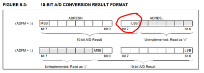
    ADCON0bits.ADFM = 0;        //ADC result is left justified
    ADCON0bits.VCFG = 0;        //Vdd is the +ve reference
    ADCON1bits.ADCS = 0b0011;    //Fosc/8 is the conversion clock
                                //This is selected because the conversion
                                //clock period (Tad) must be greater than 1.5us.
                                //With a Fosc of 4MHz, Fosc/8 results in a Tad
                                //of 2us.
    ADCON0bits.CHS = 2;         //select analog input, AN2
    ADCON0bits.ADON = 1;        //Turn on the ADC


    while(1)
    {
        __delay_us(5);              //Wait the acquisition time (about 5us).

        ADCON0bits.GO = 1;          //start the conversion
        while(ADCON0bits.GO==1){};  //wait for the conversion to end


        PORTB = ADRESL;
        PORTC = ADRESH;
      
      
    }

    return 0;
}


In this attached image, I want to get the remaining 2 bits from ADRESL and output it on RC6 and RC7
 

Attachments

  • image_2023-03-25_150545423.png
    image_2023-03-25_150545423.png
    20.7 KB · Views: 69
Last edited:
Here is a similar project using arduino nano: https://www.pcbway.com/project/shareproject/The_Crazy_Pots_Game.html

The basic principle is, you have to connect the POT to an ADC channel of the PIC16F690. You have to read the voltage of that pin with the variation of the POT. 12 LEDs will be connected to 12 output pins. I think that is what you're trying to do in your code. How is your setup behaving after you upload your code to the microcontroller?
Thank you for this I'll try to check this out
 
Your "_delay(5);" does nothing useful. It certainly doesn't allow time for the conversion because you haven't started it at that point. The GO_DONE flag will not reset until the conversion has finished so "while(ADCON0bits.GO==1){};" is already providing all the delay you need.

I suspect the problem you are seeing is because the ADRESL byte is being sent to PORTB instead of PORTC. When you left justify the result the two least significant result bits are the highest bits in ADRESL.

Brian.
 
Possibly irrelevant but looking at Example 9-1 in the MCU datasheet I note that they read ADRESH first and then ADRESL. I know that on some modules where the MCU is 8-bit but the data value is 16-bit that reading the high byte latches the low byte so you get consistant readings. Probably not the case here as the data will be latched after the A/D conversion but something to keep in mind in other situations - always floow the examples in the datasheet.
Susan
 

LaTeX Commands Quick-Menu:

Similar threads

Part and Inventory Search

Welcome to EDABoard.com

Sponsor

Back
Top