The Setlaz
Newbie level 3
Hello,
I have some issues in designing an opamp to use it as switched cap integrator in an Δ∑ ADC. The process is CMOS 65nm
Context - introduction :
This 14-bits ADC will be used as "Built-in Self Test" for a 10-bits DAC - the analog input signal speed is not determined and can be AS LOW AS I WANT. I arbitrarly choose the analog input signal speed at 1kHz with a 1024 OSR - first-order loop filter - 1-bit quantizer. So, the modulator should operate at about 1MHz.
The latched-comparator and the 1-bit quantizer are already designed and have a lot more bandwidth (they could easily operate to 50MHz and more). If I can run the Δ∑ modulator at 10MHz clock-speed, it would be even better !
So here is the problem :
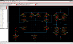
I went for a fully differential current-mirror opamp with wide swing cascode current mirrors (as showed in Ken Martins book) with leverage : see "opamp.png"
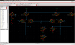
The Common-Mode Feedback Circuit is included : see "CMFB.png"
The opamp circuit in AC analysis (CMFB connected) gives me :
Open Loop Gain : 63dB
-3dB Bandwidth : 11MHz
Unity Gain : 1.61GHz
Phase Margin : -78deg
So I used 2pF Cc from output to ground as compensation.
The new results for the opamp are :
Open Loop Gain : 63dB
-3dB Bandwidth : 85kHz
Unity Gain : 105MHz
Phase margin : 52deg
These new cap of course affected the CMFB performances as follow :
The feedback circuit with "stb analysis" gives me :
Loop Gain : 49dB
-3dB Bandwidth : 85kHz
Unity Gain : 25MHz
Phase margin : 84deg
=> I see I will have some troubles if I have > 25MHz common mode input in my full diff amplifier.
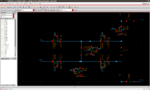
But when I close the whole loop with the switched-cap circuits (see "switched-cap.png" - there is only one represented on the screenshot, but the other one for fully differential operation is right under), it doesn't work and I have a lot of installability and common-mode issues, I don't even know where to start to analyze the Tran results (see "tran.png")
I'm very new to IC Design and I'm out of idea to solve all these problems of bandwidth and stability
Thank you in advance !
PS : everything works fine with an ideal opamp of course !
I have some issues in designing an opamp to use it as switched cap integrator in an Δ∑ ADC. The process is CMOS 65nm
Context - introduction :
This 14-bits ADC will be used as "Built-in Self Test" for a 10-bits DAC - the analog input signal speed is not determined and can be AS LOW AS I WANT. I arbitrarly choose the analog input signal speed at 1kHz with a 1024 OSR - first-order loop filter - 1-bit quantizer. So, the modulator should operate at about 1MHz.
The latched-comparator and the 1-bit quantizer are already designed and have a lot more bandwidth (they could easily operate to 50MHz and more). If I can run the Δ∑ modulator at 10MHz clock-speed, it would be even better !
So here is the problem :
I went for a fully differential current-mirror opamp with wide swing cascode current mirrors (as showed in Ken Martins book) with leverage : see "opamp.png"
The Common-Mode Feedback Circuit is included : see "CMFB.png"
The opamp circuit in AC analysis (CMFB connected) gives me :
Open Loop Gain : 63dB
-3dB Bandwidth : 11MHz
Unity Gain : 1.61GHz
Phase Margin : -78deg
So I used 2pF Cc from output to ground as compensation.
The new results for the opamp are :
Open Loop Gain : 63dB
-3dB Bandwidth : 85kHz
Unity Gain : 105MHz
Phase margin : 52deg
These new cap of course affected the CMFB performances as follow :
The feedback circuit with "stb analysis" gives me :
Loop Gain : 49dB
-3dB Bandwidth : 85kHz
Unity Gain : 25MHz
Phase margin : 84deg
=> I see I will have some troubles if I have > 25MHz common mode input in my full diff amplifier.
But when I close the whole loop with the switched-cap circuits (see "switched-cap.png" - there is only one represented on the screenshot, but the other one for fully differential operation is right under), it doesn't work and I have a lot of installability and common-mode issues, I don't even know where to start to analyze the Tran results (see "tran.png")
I'm very new to IC Design and I'm out of idea to solve all these problems of bandwidth and stability
Thank you in advance !
PS : everything works fine with an ideal opamp of course !