slessard
Newbie

- Joined
- Feb 17, 2015
- Messages
- 1
- Helped
- 0
- Reputation
- 0
- Reaction score
- 0
- Trophy points
- 1
- Activity points
- 15
Hello,
I'm designing a sensor analog chain ending to an ADC from TI (ADS6442 : https://www.ti.com/lit/ds/symlink/ads6442.pdf). The Drive CIrcuit Requirements (p49) says :
"the drive circuit may have to be designed to provide a low insertion loss over the
desired frequency range and matched impedance to the source. While doing this, the ADC input impedance has
to be taken into account. Figure 84 shows that the impedance (Zin, looking into the ADC input pins) decreases at
high input frequencies. The smith chart shows that the input impedance is capacitive and can be approximated
by a series R-C upto 500 MHz."
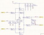
I chose a THS4520 opamp with a differential output to drive the ADC, like this :

The sampling frequency is 20MHz.
How do I design my ADC driver to ensure a low insertion loss and match the impedance of the source?
The datasheet also says that "it is necessary to present low impedance (< 50 Ω) for the common mode switching currents. For
example, this is achieved by using two resistors from each input terminated to the common mode voltage (VCM)."
I can't figure out how to mix these 3 requirements for my ADC input...
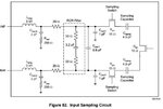
The input circuit of the ADC is as follow :

Thanks for your help!
I'm designing a sensor analog chain ending to an ADC from TI (ADS6442 : https://www.ti.com/lit/ds/symlink/ads6442.pdf). The Drive CIrcuit Requirements (p49) says :
"the drive circuit may have to be designed to provide a low insertion loss over the
desired frequency range and matched impedance to the source. While doing this, the ADC input impedance has
to be taken into account. Figure 84 shows that the impedance (Zin, looking into the ADC input pins) decreases at
high input frequencies. The smith chart shows that the input impedance is capacitive and can be approximated
by a series R-C upto 500 MHz."
I chose a THS4520 opamp with a differential output to drive the ADC, like this :

The sampling frequency is 20MHz.
How do I design my ADC driver to ensure a low insertion loss and match the impedance of the source?
The datasheet also says that "it is necessary to present low impedance (< 50 Ω) for the common mode switching currents. For
example, this is achieved by using two resistors from each input terminated to the common mode voltage (VCM)."
I can't figure out how to mix these 3 requirements for my ADC input...
The input circuit of the ADC is as follow :

Thanks for your help!
