Continue to Site

Welcome to EDAboard.com

Welcome to our site! EDAboard.com is an international Electronics Discussion Forum focused on EDA software, circuits, schematics, books, theory, papers, asic, pld, 8051, DSP, Network, RF, Analog Design, PCB, Service Manuals... and a whole lot more! To participate you need to register. Registration is free. Click here to register now.

[SOLVED] ADC application circuit

Status
Not open for further replies.

aminpix

Advanced Member level 4
Joined
Sep 30, 2008
Messages
108
Helped
2
Reputation
4
Reaction score
2
Trophy points
1,298
Activity points
2,342
I have a design with max19507. It seems the default analog input (ADC input) is between 0.4 and 1.4V. (I have connected IN- to ground and IN+ to the input signal.)

Is there anyway to change the input analog range to 0 - 2.5v? In page 15 of the datasheet it has been described but I am not sure I understand it or not. If I connect REFIO pin to 2.5v the voltage range will change to 0 - 2.5v?

Am I right?

Here is the link of the datasheet

https://datasheets.maximintegrated.com/en/ds/MAX19507.pdf
 

Hi,

i think you misunderstood the datasheet.
Reference voltage is 1.25V. External or internal, in either case. The range is very limited to +5/-15 percent. 2.5V is definitely not alloed.

There is a common mode input voltage range of 0.4...1.4V. So connecting one input to 0V is not allowed.
There is a differential input voltage range of 1.5Vpp. It means +/- 0.75Vp

The input aplication schematics are AC coupled. You can´t measure DC with them.
If you need DC, then i recommend to use an input buffer similar to LTC6263.

Klaus
 
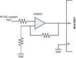
For DC coupling I plan to use this circuit. MAX19507.jpg

Does it works?

And about the voltage range, what is "+5/-15 percent"? does it mean I can have 1.25 Vpp ?
 

Hi,

did you read this?

There is a common mode input voltage range of 0.4...1.4V. So connecting one input to 0V is not allowed.
There is a differential input voltage range of 1.5Vpp. It means +/- 0.75Vp

The input aplication schematics are AC coupled. You can´t measure DC with them.
If you need DC, then i recommend to use an input buffer similar to LTC6263.

Klaus
 

How to use LTC6263 ?
 

Hi,

Sorry, it is LTC6362. Read datasheet. It is explained very wel.

If after reading still something is unclear, ask again.

Klaus
 
Status
Not open for further replies.

Similar threads

Part and Inventory Search

Welcome to EDABoard.com

Sponsor

Back
Top