pardner
Newbie level 6
Hi all, I need some help with a redesign. The existing design uses two AD9701 video DAC to adjust an incoming video signal's gain and offset and then it uses a AD9048 to digitize the signal and dump it on an 8-bit data bus and saved in RAM. The AD9701s are not used to generate a video signal, but a ADV7125 is used to reconstruct the digitized video for a test monitor. Both the AD9701 and the AD9048 are obsolete and I cannot find a direct replacement.
I need some help with their theory of operation.
AD9701
The AD9701 is running on -5.2V and the data sheet says that Vout (with 10%Bright) is -0.6375V. Analog suggests the AD9708 as a replacement, but how do I get -0.6375 out of a chip running on +5V and has a +1.2V internal reference? My quick fix was to put an op-amp on the output with -0.53125 gain. I just want to be sure that this is the correct behavior of the AD9701. (Also, I went with the ADV7125 because there was already one on the board, and a -0.327 gain amp stage).
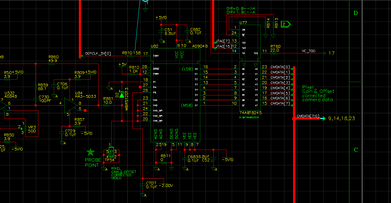
AD9048
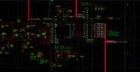
This is the one I need some help on. It is running on ±5V, Rb is connected to -2V, and the video signal is fed into Vin and RT is grounded. My problem is, I don't know what level video signal is at. Page 7 of the AD9048 datasheet shows the input ranges in the truth table: they are all negative. Analog suggests the AD9057, but it runs on a single +5V supply and an internal +2.5V reference. So I fail to see how this device would be able to sample a negative signal. Could I simple add another negative gain op-amp to switch it up to a positive signal? Here is the schematic for the AD9048:
I should also note, I do not have a functioning board available. I am working solely from schematics and a busted board. I would love to get a scope on the signals and actually see what I am getting, but I cannot.
I appreciate your help, this is the first time I have had to deal with video signals like this.
I need some help with their theory of operation.
AD9701
The AD9701 is running on -5.2V and the data sheet says that Vout (with 10%Bright) is -0.6375V. Analog suggests the AD9708 as a replacement, but how do I get -0.6375 out of a chip running on +5V and has a +1.2V internal reference? My quick fix was to put an op-amp on the output with -0.53125 gain. I just want to be sure that this is the correct behavior of the AD9701. (Also, I went with the ADV7125 because there was already one on the board, and a -0.327 gain amp stage).
AD9048
This is the one I need some help on. It is running on ±5V, Rb is connected to -2V, and the video signal is fed into Vin and RT is grounded. My problem is, I don't know what level video signal is at. Page 7 of the AD9048 datasheet shows the input ranges in the truth table: they are all negative. Analog suggests the AD9057, but it runs on a single +5V supply and an internal +2.5V reference. So I fail to see how this device would be able to sample a negative signal. Could I simple add another negative gain op-amp to switch it up to a positive signal? Here is the schematic for the AD9048:
I should also note, I do not have a functioning board available. I am working solely from schematics and a busted board. I would love to get a scope on the signals and actually see what I am getting, but I cannot.
I appreciate your help, this is the first time I have had to deal with video signals like this.
Last edited: