yannik33
Member level 1

- Joined
- Oct 18, 2011
- Messages
- 34
- Helped
- 0
- Reputation
- 0
- Reaction score
- 0
- Trophy points
- 1,286
- Activity points
- 1,507
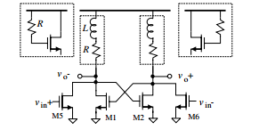
How does an active inductor (see Fig.) improve the slew-rate of a signal? In the s-domain the transfer function possess an additional zero and pole but it'd be really kind if you could explain it to me in a way more related to the actual components.
Isn't the idea that for an large di/dt (i.e. that means that the signal posses high frequency components, e.g., unitstep(t) ->1/2 {dirac(f)+1/(j*pi*f)} ) the nmos cuts the path to vdd so that the output capacitance is charged faster,i.e. the output voltage reaches the resp. level faster,too. and cos Zgs becomes quite small for high frequencies it shortens the nmos to the resitor path ergo the current flows to Cload and for low frequencies the nmos is diode connected with a small impedance (1/gm)... is this correct?

Isn't the idea that for an large di/dt (i.e. that means that the signal posses high frequency components, e.g., unitstep(t) ->1/2 {dirac(f)+1/(j*pi*f)} ) the nmos cuts the path to vdd so that the output capacitance is charged faster,i.e. the output voltage reaches the resp. level faster,too. and cos Zgs becomes quite small for high frequencies it shortens the nmos to the resitor path ergo the current flows to Cload and for low frequencies the nmos is diode connected with a small impedance (1/gm)... is this correct?

