Continue to Site

Welcome to EDAboard.com

Welcome to our site! EDAboard.com is an international Electronics Discussion Forum focused on EDA software, circuits, schematics, books, theory, papers, asic, pld, 8051, DSP, Network, RF, Analog Design, PCB, Service Manuals... and a whole lot more! To participate you need to register. Registration is free. Click here to register now.

Active Harmonic filter

Status
Not open for further replies.

katsar

Newbie level 5
Joined
Dec 10, 2012
Messages
9
Helped
0
Reputation
0
Reaction score
0
Trophy points
1,281
Activity points
1,342
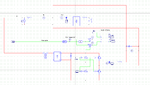
Hello. I have to desing and build for my last semester an active harmonic filter. I have desinged it in simulation and now I'm trying to make what happen in simulation real. So here is the problem. Basically many problems. I 've managed to build the control circuit. The basic concept is this: A current sensor gives me the current. This current brings odd harmonics and 50 Hz. So I am using a 50Hz band stop filter so that the output of the filter will be the Ireference for the inverter. The inverter has to create this Iref and put it back to the line before the load. This isn't very simple. I have only two months and I don't know If I'm going to make it. So I need your help, if someone of you knows anything about harmonic filters, or if how to built them, or how can i built the inverter. Any help will be appreciated. Thank you. Sorry for my poor English.
 

Attachments

  • Filter.png
    Filter.png
    36.6 KB · Views: 92

In the absence of your harmonic injection, the current flowing into mains transformer for the main DC will be a series of pulses, whose width will be dependent on the angle of conduction of the DC rectifiers "pumping" up the reservoir capacitor. Which in turn is dependent on its value and the DC load. The area under the pulse is dependent on the DC current. So one way of reducing the harmonic content would be to load the input circuit when the real DC power pulse is absent, so the input current is a sine wave. This would need a great deal of power to be dissipated. putting in some figures for a 12V 30A PSU, with no reservoir cap, In ~ 12/240 X 30 = 1.5A. With a cap and a conduction angle of 20 degrees, this current would be 1.5 X 180/20 ~ 13.5 A for a square pulse, say 20A for the semi triangular actual pulse. So your kit must "fill in" the missing part of the sine wave. Two triangular pulses per mains half cycle, each 80 degrees long and peak amplitude 15A or so, or a mean current of 80/90 X 15X .5 = 6 A !! So to keep the input current a sine wave, your kit must dissipate 6 A on average with the current being diverted to provide 1.5A real power for the DC output.
It would seem that the best approach is to get the diode on time to be as long as possible as this will result in your kit dissipating less power. The other way would be to reduce the reservoir capacitor but then the output ripple will increase.
Frank
 
  • Like
Reactions: katsar

    katsar

    Points: 2
    Helpful Answer Positive Rating
Status
Not open for further replies.

Similar threads

Part and Inventory Search

Welcome to EDABoard.com

Sponsor

Back
Top