Continue to Site

Welcome to EDAboard.com

Welcome to our site! EDAboard.com is an international Electronics Discussion Forum focused on EDA software, circuits, schematics, books, theory, papers, asic, pld, 8051, DSP, Network, RF, Analog Design, PCB, Service Manuals... and a whole lot more! To participate you need to register. Registration is free. Click here to register now.

Active filter Design

Status
Not open for further replies.

MichaelHelal

Newbie
Joined
Oct 9, 2020
Messages
5
Helped
0
Reputation
0
Reaction score
0
Trophy points
1
Activity points
55
How can i extract the required GBW and the TF for two-stage miller amplifier implemented in a complex filter design?
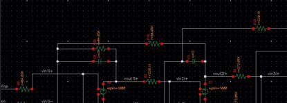
I am designing a complex filter that uses 2 stage miller amplifier
I have a problem how to extract the GBW of the amplifier since its load is not a capacitor, as usual, it's a resistor?
and also the amplifier is placed in feedback to act as an integrator "having a capacitor and resistor in feedback"
 

Attachments

  • opamp ideal.jpg
    opamp ideal.jpg
    75.8 KB · Views: 92

I have difficulties to relate the posted schematic to your question. The simulation circuit (unfortunately an incomplete snippet) uses ideal controlled voltage sources, respectively they neither have a GBW nor is the transfer function load dependent.

Non ideal amplifiers modify the filter transfer characteristic by certain extent. Minimal GBW numbers are just a rule of thumb, you still have to look at the actually achieved filter characteristic and usually need to tune component parameters. The GBW poles create a modified transfer function in any case, there's no way to achieve the intended ideal filter function exactly.
 

Status
Not open for further replies.

Similar threads

Part and Inventory Search

Welcome to EDABoard.com

Sponsor

Back
Top