Continue to Site

Welcome to EDAboard.com

Welcome to our site! EDAboard.com is an international Electronics Discussion Forum focused on EDA software, circuits, schematics, books, theory, papers, asic, pld, 8051, DSP, Network, RF, Analog Design, PCB, Service Manuals... and a whole lot more! To participate you need to register. Registration is free. Click here to register now.

Accelerometer circuit design

Status
Not open for further replies.

voultsi

Newbie level 6
Joined
Jun 23, 2014
Messages
11
Helped
0
Reputation
0
Reaction score
0
Trophy points
1
Activity points
104
Hello people ,
I dont know if my question is under the correct category but anyway

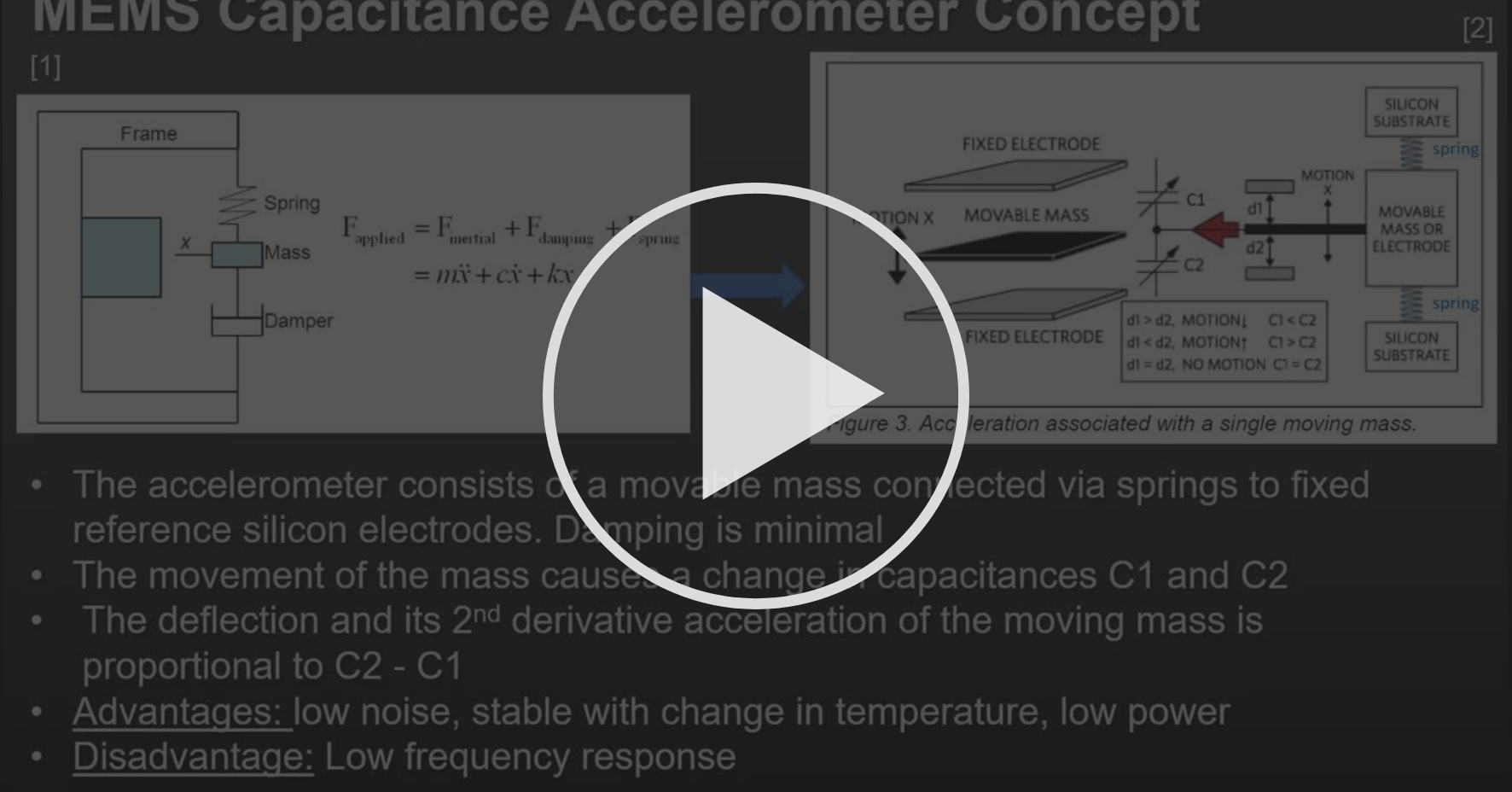
I need to design a very basic accelerometer circuit . The point is to take the voltage measuerement that a capacitive accelerometer provides and after proccessing it to output it .
The circuit will probably only consist of a few capacitors and resistors , an A/D converter ,an amp and integrators.
I have searched a lot online and have found very few info about such a topic , most are about the construction of the accelerometer. I have a some knowledge about op-amps(integrator,differentiator) and signals.
So if anyone can explain how and why things happen i would be very happy.

P.S i am talking about a diagram not any actual sensors , its more about understanding the concept


That what you are looking for ?


Regards, Dana.


That what you are looking for ?


Regards, Dana.
Not exactly but still thank you!
 

Thank you very much for your answers , i am really happy that i can find some assistance and i will try to clarify the best i can.

The accelerometer will be designed from the start. Only the capacitors are available and their output

The method is referred as differential capacitive sensing.

The output of the capacitors needs to get into a differential op-amp or a transimpedence amplifier so we can get the difference. After getting this measumerement, we need to make it as linear as possible and nullify any parasitic capacitance(miller theorem?)

I guess :
The linearity will be achieved with some sort of feedback loop
The parasitic capacities will be nullified by a cascode

As an output , we need the g force measurement in digital form(A/D converter)
Any kind of filter and op amp can also be used .

I am trying to form the question as clearly as possible but since i do not understand it very well it is somewhat diffucult to do so.

P.S By the way , this was a question for better understanding sensors in my class of microelectronics and i have started studying it again because i finally got into my sector.. but while i can get the grasp of it , i cant form a whole answer.

Characteristics: the accelerometer needs to measure up to 50g for an airbag
inside a car that constanly produces up to 2g . Frequency range of the sensor
should be 400Hz .
 

For filtering you can use a PSOC 5LP which will add DSP to the components discussed
earlier in the examples. Again. onchip. A wizard is used to set it up, this is one of the examples
in the IDE -

PSOC Filter.PNG


PSOC Filter Wizard.PNG


Regards, Dana.
 

For linearization you could use the onboard UDB engine, a high speed
programmable ALU, to do curve fitting on data, like least squares or
power curve error fitting/correction approaches. Or just C code if latency
not an issue.

PSOC Datapath.PNG


Regards, Dana.
 

Sensor, use in a bridge, excite bridge with A/C and sample with DelSig (since design is
only good for 400 Hz) you can do 16 - 18 bits with it to give you good resolution.


Regards, Dana.
 

Well Dana , you gave me a lot of "homework" to study on . Thank you very much for the effort , your answer is very detailed and i am very grateful. I am not familiar with PSoC creator , so i will need time to understand your answer. You get the analog signal in the ADC , then you get the digital signal in the DMA so you can transfer it to the output through a VDAC that regulates the range of voltage in the output and outputs an analog signal. I will try to understand why you use the filter and why convert the signal first to digital(for the filter?) then to analog again .
Thanks again for the answers , they are going to help me a lot !!!!
 

The "normal" process of digital filtering is to take a signal, convert it from analog to
digital, process it, then return it to analog. Analog being continuous time domain,
fancy word for a signal as defined here -


Sometimes one does not need to do the back end conversion to analog, example
when seeking a peak value out of a filter just look at magnitude of samples coming
back out of filter, no need to do that in analog domain.

The other big advantage to DSP processing is filter realization, especially in high order
filters where component tolerances and drift short and long term make it impossible
to make a "brick wall" filter.

The DMA process used here are to take samples from A/D and pass them into the filter
for processing. DMA offloads the CPU from having to do this via code, which causes
latency and un-necessary burden on CPU.
I am starting to get a better understanding of the circuit. Your sampling rate is 48kHz if i understand correctly , you chose that because it is about 100times more than the bandwidth ? Or am i completely wrong ?
And your low pass filter is at 6kHz , that is something i dont understand why. You use the LP filter to filter out noise? If that is so , why 6kHz?
About the DSP, i get why you do the conversions , i got a little bit confused before...

Thanks for the answers!!
 

The filter is a completely arbitrary example, ignore its parameters. I showed this
because you mentioned in an earlier post you would need filtering. You would change
the sampling rate and cutoff and type......for your specific design needs. Nominally you
would start with a sample rate 10x cutoff and optimize from there. Or use one of the
design programs out on WWW and give it design goals, tool would then generate
optimal sample rate and order......


Regards, Dana.
Ok , great , i understand what you are saying . But , what cutoff frequency would be appropriate to use for such a system? Is it logical to say that since we want a bandwidth of 400Hz that the cutoff frequency of the LP would be 400Hz ? The use of the LP is to cutoff noise, so we assume that any input with more than 400Hz is noise , is this right ?
 

Last edited:

Ok , i believe i have most of the circuit figured out , thanks . I will see the videos about the PSOC , thanks for the link .
Anyways, thanks for the feedback , it has been very helpful . Thanks !!
 

Status
Not open for further replies.

Similar threads

Part and Inventory Search

Welcome to EDABoard.com

Sponsor

Back
Top