fang
Newbie level 1

- Joined
- May 2, 2013
- Messages
- 1
- Helped
- 0
- Reputation
- 0
- Reaction score
- 0
- Trophy points
- 1,281
- Activity points
- 1,293
Hey guys, you'll have to lead me through this. I know nothing of diodes etc. My background is 12 volt DC automotive stuff.
My hot rod has a GM 700R4 transmission with the GM vss running an autometer electric speedometer. The vss has 2-wires, and generates a four-pulse (4000 pulses per mile) sine-wave (A.C. current) with minimum voltage of 1.8 volts and the signal climbs proportionately with vehicle speed.
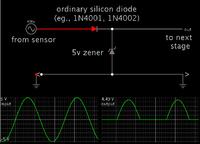
I would like to convert the AC sine wave to a DC square wave with a voltage of 0-5 volts (most senors are 0-5 volts on computer equiped cars) so I can connect my innovate LM2 to it so I can record MPH along with the AFR and RPM that the LM2 records. The LM2 has connections for analog input and output. The LM2 already does this through an OBD2 connection but this hot rod has no OBD2 connection as it has no ECM.
This is not something that will be mounted permanently in the car if that helps.
Thanks for all your help guys!

