Continue to Site

Welcome to EDAboard.com

Welcome to our site! EDAboard.com is an international Electronics Discussion Forum focused on EDA software, circuits, schematics, books, theory, papers, asic, pld, 8051, DSP, Network, RF, Analog Design, PCB, Service Manuals... and a whole lot more! To participate you need to register. Registration is free. Click here to register now.

AC Sensing with microcontroller dspic30f5011

Status
Not open for further replies.

gravi

Full Member level 2
Joined
May 30, 2006
Messages
128
Helped
10
Reputation
20
Reaction score
10
Trophy points
1,298
Location
Hyderabad, India
Activity points
2,452
Hi everyone,

Hi,
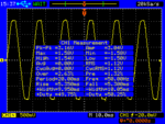
We are trying to read AC 230 Volts using an Op-Amp MCP6292 and Output is interfaced with dSPIC30F5011, The Output is 2.5 Volts Sinusoidal wave, When opamp output is tested with multimeter we could find 2.5V dc and 0.94 v AC. 2.5 V dc remains same from 0 - 280 Volts AC, AC output voltage varies proportional to Input Voltage. We were able to read 2.5 V DC using micro controller adc, we are trying to read AC voltage. Is there any other process involved in reading AC voltages. Please find the oscilloscope screen shot also attached.

Thanking You,
Ravi Kumar G
 

Attachments

  • SCOPE_00.png
    SCOPE_00.png
    10.2 KB · Views: 76

If I am right,I guess the 2.5 volts DC is the offset voltage and the AC your mentioning (0.94 v ) is the added voltage to it due to Ac voltage variation, my suggestion is, you may have to adjust the gain of the opamp by adjusting feedback resistor in the hardware circuit to get better response on the AC voltage. The offset voltage (2.5 v dc)adc value you should subtract from the actual value your getting from the port.

hope this may help you ..
 

Dear Mr.Ravi,
Measuring AC signal is little difficult compared to DC signal.
You may try two methods.
1. Rectify and Average your AC Voltage to DC using hardware diode, series resistor and cap to GND. Measure the DC at cap and calibrate it to RMS.
2. RMS method: Sample the signal as many as possible ( around 128 samples in 20ms period ) and store them in buffer. Perform mathematical RMS calculation to the samples. Steps-> Substract offset, square each sample and add, average it then get square root.
You will get good stable RMS value of the signal.

Regards
Tirumala Rao
 

Yes I agree with Tirumala Rao, RMS calcuation method is best, and I also use the same. The DC offset clamping voltage you should subtractfrom the actual read value in the firmware, and the adc sampling period also should be high.
 

Dear Mr.Ravi,
Measuring AC signal is little difficult compared to DC signal.
You may try two methods.
1. Rectify and Average your AC Voltage to DC using hardware diode, series resistor and cap to GND. Measure the DC at cap and calibrate it to RMS.
2. RMS method: Sample the signal as many as possible ( around 128 samples in 20ms period ) and store them in buffer. Perform mathematical RMS calculation to the samples. Steps-> Substract offset, square each sample and add, average it then get square root.
You will get good stable RMS value of the signal.

Regards
Tirumala Rao

Dear Sir,
We are doing RMS Method, but we have captured only 4 samples in a sinewave i.e for 20ms. As suggested we will try with more than 100 samples in 20ms period. Could you please explain me more about subtract offset.

Thanking You,
Ravi Kumar G
 

Hi
I was mentioning the DC offset voltage your seeing at the adc that you should subtract from the actual reading and take it to the RMS averaging.
 

Dear Anand,

What exactly is DC offset Voltage.

Thanking You,
Ravi Kumar G


Hi,

We have tried with 1st Method suggested by you, Our program was as mentioned below
Step 1: Read/Capture ADCBUFF Value for every 156 micro Second.
Step 2: Remove DC-Offset from from ADCBUFF each time we read channel
Step 3: Applied RMS formula for 128 Samples.
Step 4: RMS_ADCBUFF is converted to Voltage by multiplying with 5/4096 i.e Operating Voltage/12 bit adc.
Step 5: OP_temp_Volt is then multiplied by multiplication factor to obtain Real time Voltage.

But the final output is +/- 5 Volts i.e if my input voltage is 160V AC, with our program we could read 155Volts to 165 Volts volatile value.

Is their any other process to overcome this or Am I totally wrong with procedure


Thanking You,
Ravi Kumar G
 

Dear Folks,

We were able to read AC Voltages successfully with +/- 0.5 Volts difference and Read 3 Phase Voltages with respect to Neutral as well. I Knew that Multiplying Phase to Neutral Voltage with 1.732 i.e Squareroot of 3 would give us line to line Voltage but How to calculate when Phase to Neutral Voltages are not same for all the 3 Phases.

Thanking You,
Ravi Kumar G
 

Status
Not open for further replies.

Part and Inventory Search

Welcome to EDABoard.com

Sponsor

Back
Top