Continue to Site

Welcome to EDAboard.com

Welcome to our site! EDAboard.com is an international Electronics Discussion Forum focused on EDA software, circuits, schematics, books, theory, papers, asic, pld, 8051, DSP, Network, RF, Analog Design, PCB, Service Manuals... and a whole lot more! To participate you need to register. Registration is free. Click here to register now.

AC regulation with LM317

Status
Not open for further replies.

djnik1362

Full Member level 2
Joined
Aug 9, 2010
Messages
136
Helped
1
Reputation
2
Reaction score
1
Trophy points
1,298
Location
IRAN
Activity points
2,374
Hi

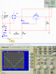
I work on a circuit that has a 24 VAC sin wave input as a reference.
This input can't be used as a supply input.

I want to design a power provider that it's output follows mentioned sin wave at positive levels.
It means my power provider voltage level must be half-sin wave at positive level.
This power provider can provide 1.5 A at voltage level 2 volt below maximum of 24 VAC input.

I must first fed this input to a Diode Bridge and then use bridge positive voltage as source for some power sections. I know that with using a LDO regulator such LM317 this scheme can be designed .

Can you help me ?

Thanks for your support.
 

It sounds as though you plan to construct a full-wave diode bridge power supply.
This is an easy and useful project.

A 24 VAC sinewave has peaks at 1.4 x (or 32V, positive and negative).
The diode bridge will convert that to entirely positive voltage.
Add a smoothing capacitor and light load, and you will measure about 31V.

The LM317 can be adjusted to regulate that figure down to 24 VDC. I believe that is your goal?

However 1.5 A is the limit of what the LM317 can provide. It will heat up.
You probably will need to add other components to share the burden.
 
The current is a bit of concern a lower resistive path in parallel to LM can take a little load off the regulator
 

It sounds as though you plan to construct a full-wave diode bridge power supply.
This is an easy and useful project.

A 24 VAC sinewave has peaks at 1.4 x (or 32V, positive and negative).
The diode bridge will convert that to entirely positive voltage.
Add a smoothing capacitor and light load, and you will measure about 31V.

The LM317 can be adjusted to regulate that figure down to 24 VDC. I believe that is your goal?

However 1.5 A is the limit of what the LM317 can provide. It will heat up.
You probably will need to add other components to share the burden.

I don't need DC voltage at output, I need an AC ( half-wave sinuous) voltage with current capacity around 1.5 A .
 

Lm317 is not ac regulator .Use transformer 24v connected at constant i/p
 

LM317 can be possibly used as a short circuit protected output stage of a "AC regulator". But I agree with the previous posts saying that it can't work as a AC regulator itself. Unfortunately you didn't describe the intended regulator operation clearly. Rather than guessing in this regard, we should just wait for a clearer specification.
 

LM 317 is a DC voltage regulator, with a low threshold of ~1.5V. Using protection diodes, you possibly can use two or four as a bridge voltage AC regulator. But there will be a distortion of the AC output at +/- 1.5 V around zero, and then peak limiting due to the DC voltage set with resistors or LM317 output.

Making AC regulators has always been difficult; in the olden times there were magnetic regulators with saturated transformers, later with vacuum tubes. Maybe it can be now done easier with AC/DC converter, a DC regulator and a DC/AC converter..
 

I don't need DC voltage at output, I need an AC ( half-wave sinuous) voltage with current capacity around 1.5 A .

I think all of us will be less confused of you explain with some drawings what the output should look like. I am not sure what you mean by "half-wave sinuous."
 

To get pulsating output from the output of the LM317.
You should feed 24v * 1.41 + dropout = 36VDC (or more) to the input of the LM317.
And the half wave rectified 24VAC must appear at the reference input of the LM317. Because the LM317 output will follow the ref input with aprox 1.27v difference.
You then will get the waveform that I understand you need at the output with some distortion near zero (because of the dropout).
A resistor from the output to the ref of the LM317 and another from the ref to the half wave rectified 24VAC should be calculated to give the correct reference and get feedback from the output. Thus achieving regulated output.
Anyway as BradtheRad said the LM317 will limit by current and by dissipation in your application. So you may need to add a power transistor to handle the power. The max power dissipated by the LM317 will be 36 * 1.5 = 54 watts.
Check the datasheets to see if it can make it.
Hope that I get you right and helped
 
That is what is confusing. He said he does not want DC. Looks like what you describe is either full or half wave pulsating DC.
 

I thought of this circuit before which will follow the input with a 2V offset, but did not post it because of the "no DC" requirement.
 

Attachments

  • regulator.gif
    regulator.gif
    103.9 KB · Views: 125
Last edited:
To get pulsating output from the output of the LM317.
You should feed 24v * 1.41 + dropout = 36VDC (or more) to the input of the LM317.
And the half wave rectified 24VAC must appear at the reference input of the LM317. Because the LM317 output will follow the ref input with aprox 1.27v difference.
You then will get the waveform that I understand you need at the output with some distortion near zero (because of the dropout).
A resistor from the output to the ref of the LM317 and another from the ref to the half wave rectified 24VAC should be calculated to give the correct reference and get feedback from the output. Thus achieving regulated output.
Anyway as BradtheRad said the LM317 will limit by current and by dissipation in your application. So you may need to add a power transistor to handle the power. The max power dissipated by the LM317 will be 36 * 1.5 = 54 watts.
Check the datasheets to see if it can make it.
Hope that I get you right and helped

Thanks . That is it . Very useful . Yes i need a pulsating power provider .

- - - Updated - - -

I thought of this circuit before which will follow the input with a 2V offset, but did not post it because of the "no DC" requirement.

very useful . Thanks.

- - - Updated - - -

Lm317 is not ac regulator .Use transformer 24v connected at constant i/p

Reference input can't be used as a power source because it's current is very low.

- - - Updated - - -

albert22 - Can i use two parallel regulator block to provide more power ? Is it possible with LM317 ? Thanks for your support.

- - - Updated - - -

E-design - Can you explain your circuit ? Thanks.
 

It can be done. But I dont advice paralleling three terminal regulators. Because it would be very difficult to balance currents and one of them may go into limit by temperature leaving the other to do the same.
A better solution is to use a LM350 (3 amp) or as a power transistor to aid the LM317.
Take care because you have to account for power disipation AND max current. Also check max input voltage.
 

The solution to this problem is having constant ac (24v) as o/p . This lm317 cannot solve this problem.
 

Status
Not open for further replies.

Part and Inventory Search

Welcome to EDABoard.com

Sponsor

Back
Top