Continue to Site

Welcome to EDAboard.com

Welcome to our site! EDAboard.com is an international Electronics Discussion Forum focused on EDA software, circuits, schematics, books, theory, papers, asic, pld, 8051, DSP, Network, RF, Analog Design, PCB, Service Manuals... and a whole lot more! To participate you need to register. Registration is free. Click here to register now.

AC open loop characteristics quires

Status
Not open for further replies.

Junus2012

Advanced Member level 5
Joined
Jan 9, 2012
Messages
1,552
Helped
47
Reputation
98
Reaction score
53
Trophy points
1,328
Location
Italy
Visit site
Activity points
15,235
Dear Friends

couple of days gone without posting a thread , the weekend is now finished and the work time started :):)

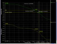
I have attached you the AC response from my designed OTA

the OTA is a current mirror OTA which I had some questions about it in other posts.
In the picture, I have pointed at the pole frequencies (-45, -135).


the first question is , after the second pole, the gain should drop by the rate of -40 dB/decade, but in my figure it is not like that, I have tested the drop and it is giving me 13 dB/decade rather.


the second question, the Gain bandwidth product is constant only when the roll off is constant , in my design the roll off is constant and it is 20 db/decade untill the unity gain point, which make the GBW constant........ what about the case if the second pole is before the unity gain bandwidth, I never hear about how to deal with GBW in this case (without using the compensation miller capacitor)


the third question, if you know the GBW, how you could determine the DC gain (please prove it from my graph)


the fourth question : the far distance of the second pole from the first one will improve the PM (increase it), this because it will push far the accumulation of the second pole phase when it become 180. However, what about if the distance between the poles are increase by decreasing the first pole position ????????????, for me I am thinking it must degrade the phase margin coz the phase shift will approach the 180 earlier ..... practically is the reverse I am finding


Thank you all in advance
 

Attachments

  • AC.JPG
    AC.JPG
    206.5 KB · Views: 137

.. after the second pole, the gain should drop by the rate of -40 dB/decade, but in my figure it is not like that, I have tested the drop and it is giving me 13 dB/decade rather.

Hi Junus, welcome back again.
I didn`t calculate the gain drop after the second pole in detail - however, it seems to me that the drop in any case is larger than after the first pole (-20 dB(dec).
That means: Do you still read 13 dB/dec?
 

Dear LvW

I attached you two cursors at the decade after the second pole

Thank you


Hi LvW

too much of questions are waiting for you, its a little hard after the holiday :):)
 

Junus, I do not need any cursors to see that the magnitude of the gain slope after the 2nd pole is larger than before this pole. Don`t you agree?
 

Ok, I agree

now some questions left for you from the first post :) :) , I will still remind you Sir until you kindly answer me all :)


Junus, I do not need any cursors to see that the magnitude of the gain slope after the 2nd pole is larger than before this pole. Don`t you agree?
 

Hi Junus,
here are some answers:
* first question solved
* second question: For single pole roll-off (-20dB/dec) GBW=transit frequency Ft (in your case approx. 2 MHz). In case the 2nd pole is below the unity-gain frequency the GBW would be the same (1E4*0.2kHz).
(By the way: I believe that - in addition to the Ft - the term GBW was introduced in particular for those cases where the 2nd pole is below the unity gain frequency).
* third question:To determine the dc gain from the known GBW you need to know also the 1st pole frequency
* 4th question: "...I am finding..." How did you find out? I think, the variation of the PM can be neglected.
 
Guten Tag LvW :)

the third question : yes of course I need at least the first pole frequency , but suppose if I have very high DC gain that I can not detect the pole frequency gain , what is the alternative method will be ?? any way I will post this problem in another thread so you can answer here or there (I prefer both :) :) :) )

regarding the 4th qquestion..... for the self biasing OTA like the current mirror , folde and telescopic OTA, the output pole is the dominant. thus the f-3dB =1/2.pi.Ro.... in the same time, these OTAs becomes more stable when the capacitive load increase, it mean when decreasing the first pole. here is what I would like to know, why when the first pole be at the smaller frequency, the circuit is more stable ??????? anyway I would also post this in another thread so you can post here or there...... you always welcome


Hi Junus,
here are some answers:
* first question solved
* second question: For single pole roll-off (-20dB/dec) GBW=transit frequency Ft (in your case approx. 2 MHz). In case the 2nd pole is below the unity-gain frequency the GBW would be the same (1E4*0.2kHz).
(By the way: I believe that - in addition to the Ft - the term GBW was introduced in particular for those cases where the 2nd pole is below the unity gain frequency).
* third question:To determine the dc gain from the known GBW you need to know also the 1st pole frequency
* 4th question: "...I am finding..." How did you find out? I think, the variation of the PM can be neglected.
 

Junus,

@3) I suppose you know the gain at a certain frequency (thus you have the GBW). From this knowledge you are not able to derive the dc gain or the first pole frequency.
@4) When the gain starts to drop down at a smaller frequency it will go through the 0 db line also at a lower frequency. Thus, the phase shift at this smaller frequency will be also somewhat smaller (just a little!).
 
Dear LvW

Thank you for your fast response

for Q4, according to your explanation the phase margin is getting degraded which I am also thinking. practically is the reverse, I have a self compensated OTA and whenever I increase the load capacitance, the phase margin improves... you can find this also by any kind of text book

Thank you very much

Junus,

@3) I suppose you know the gain at a certain frequency (thus you have the GBW). From this knowledge you are not able to derive the dc gain or the first pole frequency.
@4) When the gain starts to drop down at a smaller frequency it will go through the 0 db line also at a lower frequency. Thus, the phase shift at this smaller frequency will be also somewhat smaller (just a little!).
 

for Q4, according to your explanation the phase margin is getting degraded which I am also thinking.

Oh no - just the opposite.
Read what I have written: the phase shift at this smaller frequency will be also somewhat smaller

A smaller phase shift means more distance to the limit and, thus, more margin.
 
Ok Ok, I got it, the phase margin is improving in the cost of smaller GBW

Thank you very much

Oh no - just the opposite.
Read what I have written: the phase shift at this smaller frequency will be also somewhat smaller

A smaller phase shift means more distance to the limit and, thus, more margin.

- - - Updated - - -

your answer led me to another idea

According to this , low bandwidth frequency are easier to compensate than of th wide bandwidth , right ?
 

Status
Not open for further replies.

Part and Inventory Search

Welcome to EDABoard.com

Sponsor

Back
Top