Continue to Site

Welcome to EDAboard.com

Welcome to our site! EDAboard.com is an international Electronics Discussion Forum focused on EDA software, circuits, schematics, books, theory, papers, asic, pld, 8051, DSP, Network, RF, Analog Design, PCB, Service Manuals... and a whole lot more! To participate you need to register. Registration is free. Click here to register now.

About the Bitmap/Jpeg to pixel array converter software

Status
Not open for further replies.

Deepak Rathore

Member level 2
Joined
Apr 25, 2012
Messages
46
Helped
0
Reputation
0
Reaction score
0
Trophy points
1,286
Activity points
1,659
hello friends,

currently i am working to on the TFT color Display to display the color images on the TFT Display.

I have TFT color display(320x240).i want to display the color image on my TFT display.
so how can i display that color image. how can i convert the color image into the Pixel array format.
from where i download that converter software.

and how can i send that color array information to the TFT LCD. i have 8 bit data lines for the LCD data port.

if anyone have worked on it,then please help me on this problem.

Deepak
 

I can only help you with the image conversion.

You can use for example imagemagick convert tool (opensource) to convert the image to text format and change color format also.

convert from.png -format rgb outout.txt

This will need post-processing tho. If you've matlab with image processing toolbox you can use its functions (imread, im2gray, ...).

JF. Mousinho
 

if you want there is free lib called as FreeImage which will give you API level interface to convert the Image in to Byte array... Also as Jemos suggested you need to store that as *.txt file and read that file to get the values...

refer this -
http://freeimage.sourceforge.net/

Good Luck
 

Thnnx frnds for your reply.........

from the free bitmap to image pixel array converter software, i get my array pixel array data.
To display image on the 320x240 TFt color display,which color format am i use 2 display image to display.\
I tried use 16bit color format.but in this way i got cartoon type image on my display which have nt the true color of image.

and while i convert image convert to pixel array, i use true RGB color, then it give me just this type array converted array

Code:
const char image[] = 
{
0xFF,0xFE................
...........................
........................
}
is this pixel araay data is correct,then how it is send to the TFT LCD..

please help me

Regards
Deepak
 

What is the format your color display takes a color input.....I mean it is R G B array or three different matrix of R , G ,B....first figure it out that.....
 

hey Milind, thnx for your reply,

I have Micromedia stellaris M3(ARM cortex m3) board which have TFT Color display interfaced.so in order to display the color images on it, i think that it have RGB array which have color information of three colors in order 2 turn on one color pixel.

Deepak
 

No you are not catch my question.....I am asking you you need to send 3 matrix of R, G, B of let say 320x240 resolution to your display of a single materix of 960x720 with R G B in the them like ...In most of the cases it will be the second case

Code:
const char image[] = 
{
R1,G1,B1................
...........................
........................
}


.....I think you share the part number of your LED display

Good Luck
 

hey milind,

I am using TFT LCD display with MI0283QT2 LCD Module, having SSD2119 LCd controller and HX8347-D LCD driver IC.
it has inbuilt color control graphics engine.

and when i convert the bitmap image into pixel array......

it gives me just following table
Code:
const char image[] = 
{
0xFF,0xFE................
...........................
........................
}

in what order i need to send the pixel array table to LCD so it can cmpltly display the true color image.

and one more case, when i convert my bitmap image to 16 bit color, then it gives me the following table

Code:
const char image[] = 
{
0xFFEE,0xFE12,0x4587,................
...........................
........................
}
so i send the above pixel array values to LCD(8bits at a time),then it shows me just cartoon type image...not the true image.
so this all are my doubts...
i hope u understand what i want to say 2 you.

Regards
Deepak
 

Ahh....Now I uderstand your problem....I think you need to write first of all the interface to the HX8347-D .....did you write that piece of code....and then you can send the data to LCD properly.... But some how I feel that that would have been taken care by the OS that you are using on your processor...which OS you are using....of are you writting the driver to LCD dispaly....Can you share this information....also what I am looking at is also the code that you are written for LCD communication...

Good Luck
 

thanx milind,

hmmm.........at the start, i Init my TFT LCD by writing all the registers(like as power control,osc control,display control,gamma control,window setting register and etc..)with their respective values.... and
i write the code for the 16 bit color format as follows as

Code:
const unsigned char bmp[] = {
0xffee,0x125F,...........
...............................
...............................
}
void  drawpicture()
{
unsigned int i,j;
unsigned long int  val=0;

LCD_win(0,0,319,239);
LCDCommand(0x22);
 TFT_CS = 0;

for(i=0;i<240;i++)
{
for(j=0;j<320;j++)
{
   GPIO_PORTJ_DATA_R = bmp[val]/0X100;
   TFT_WR = 0;
   TFT_WR = 1;

 GPIO_PORTJ_DATA_R = bmp[val]%0X100;
   TFT_WR = 0;
   TFT_WR = 1;
val++;
}	
}
TFT_CS =1;

when i convert the my bmp image to 24bit true color for image,then it has the following code
the pixel array are as follows.......
Code:
const unsigned char bmp[] = {
0xff,0x12,0x45,0xf5,...........
...............................
...............................
}
void  drawpicture()
{
unsigned int i,j;
unsigned long int  val=0;

LCD_win(0,0,319,239);
LCDCommand(0x22);
 TFT_CS = 0;

for(i=0;i<240;i++)
{
for(j=0;j<320;j++)
{
   GPIO_PORTJ_DATA_R = bmp[val];
   TFT_WR = 0;
   TFT_WR = 1;
val++;
}	
}
TFT_CS = 1;
this is my code that i had done.
and i am using OS is Window XP.
 

Hi deepak,

You can try, using the 16 bit conversion output, to excange the order of the 2 write cycle ?
The color are so correct ?
 
Last edited:

once again thnx alex_r for Your reply........

but when i am trying to display image with the 16 bit conversion output,the imaqge on the output looks like as a cartoon type image,not original image that i have converted.....
so i needs to bit 2 b convert into the 24bit true color....


what i do 2 display the original color image on the display same as original color quality...
 

or using a rgb out try:
Code:
const unsigned char bmp[] = {
0xff,0x12,0x45,0xf5,...........
...............................
...............................
}
void  drawpicture()
{
unsigned int i,j;
unsigned long int  val=0;
unsigned char r,g,b;
LCD_win(0,0,319,239);
LCDCommand(0x22);
 TFT_CS = 0;

for(i=0;i<240;i++)
{
for(j=0;j<320;j++)
{
   r=bmp[val++];
   g=bmp[val++];
   b=bmp[val++];
 
  // if you have wrong color change with
  // b=bmp[val++];
  // g=bmp[val++];
  // r=bmp[val++];
  
   GPIO_PORTJ_DATA_R = ((r & 0xf8) | (g >>5));
   TFT_WR = 0;
   TFT_WR = 1;

   GPIO_PORTJ_DATA_R = ( (b & 0x1f) | ( (g & 0x1c)<<3) );
   TFT_WR = 0;
   TFT_WR = 1;
}	
}
TFT_CS = 1;
 
thanx alex_r for ur reply....
i checked the above procedure.i get the good result.the result is improved.

but i didn't get the true color image on my display.

i have doubt that is in order to turn on the pixel with it's full color, v need 2 send the three color info to LCD at a time.

but in the above code v r sending either only R and G or G and B color info to the LCD port.
so there is any other way 2 send the full color info(R,G,B) to the LCD port.

then i hope that idea will be worked.

Deepak
 

Your TFT module have the IM0 IM1 pin available to setting the bus enter mode for 256K color ?
If it do not have, the only color mode that you can use is the 64K color mode, 5bit for red ,6 bit for green, 5bit for blu
So some gradient color can be appear as fixed color in 64K mode.
The only way to improve image quality, is using 16bit ditering before you convert (photoshop can do it)
Another hint can be the Gamma correction setting in your LCD_Init
 

alex_r,

i have the IM(3:0) have the configuration is 0011.means it has the 8080 8 bit parallel interface.
and
in the above information i did not get anything what u want to say with me.
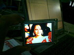
and i have also uploaded the image that i am getting in my board...
Photo0107.jpg

and one more thing is that according to yourself,what values shold be written in the gamma correction registers to obtain the real image.

please reply...

Deepak
 

Hi,

Sorry, I do not know gamma correction value for your TFT. You must find other user having the same TFT module.

But have you apply a 16 bit dithering before convert the picture as I suggest in previous post ?
 

hi alex_r,
i need ur little bit help in my project.

I am working now on the ARM cortex M3 stellaris board provided by the Mikroelectronica.

basically i have init the LCD and fill it differnt colors. it is working ok.
but when i fill it with Green,or some color hex code,then diffenrt color is filled instead the original color.
my hex color code info is this below

Code:
#define Black     0x0000                   
#define Maroon  0x8000                 
#define Olive     0x8400                  
#define Navy     0x0010                 
#define Purple    0x8010  
#define White    0xFFFF

is the hex code for the color is ok.....
am i wrong in some point....

please help me that how can i display my basic color on the LCD

Deepak
 

Hi,

As I already said, you try to swap the high byte and low byte of the color.
(depends on how you initialize the display to accept the color in RGB or BGR format)

If you fill a rectangle with color=0x001f it appear red or blue ?
 

Hey friends if you are looking for batch image converter then I have recommended you “ReaConverter”. I have great experience of working with it's. It does prove really very helpful for me while I have a bunch of images and I need to convert and resize all of them. With the help of ReaConverter can convert them all at once.
 

Status
Not open for further replies.

Part and Inventory Search

Welcome to EDABoard.com

Sponsor

Back
Top