Continue to Site

Welcome to EDAboard.com

Welcome to our site! EDAboard.com is an international Electronics Discussion Forum focused on EDA software, circuits, schematics, books, theory, papers, asic, pld, 8051, DSP, Network, RF, Analog Design, PCB, Service Manuals... and a whole lot more! To participate you need to register. Registration is free. Click here to register now.

About Dimmer Circuit designed by Sunrom Technologies

Status
Not open for further replies.

SINDHURI

Member level 2
Member level 2
Joined
Dec 13, 2012
Messages
46
Helped
0
Reputation
0
Reaction score
0
Trophy points
1,286
Visit site
Activity points
1,662
Sir, In my project i had control the intensity of the light(60W bulb)and small A.C fan upto 4 level (ON,OFF,33% and 66%)by using the module designed by sunrom technologies of MOC3021. Please explain me the operation of that dimmer triac circuit module.

Thanks in Advance
 

I assume you're talking about this module: **broken link removed**

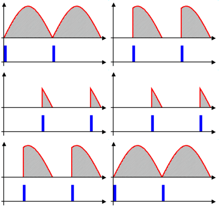
For dimming, phase angle control is used.

15_1277448873.gif


------------------------------------------------------------------------------------------------------------------

There is a chip at the bottom of the module (Datasheet: **broken link removed**) that translates the 4-bit signal from the microcontroller to a drive signal to drive the triac at different phase angles as required.

Go through this: https://www.edaboard.com/threads/181497/#post759620

Hope this helps.
Tahmid.
 

Sir, In my project i had control the intensity of the light(60W bulb)and small A.C fan upto 4 level (ON,OFF,33% and 66%)by using the module designed by sunrom technologies of MOC3021. Please explain me the operation of that dimmer triac circuit module.

Thanks in Advance
Hi Sindhuri
You can google it ! you'll find gang of pages about this issue . but i prefer to tell you a bit about it !
A triac is an alternative switch which can be turned on when command signal is incoming and it will be on till the voltage across MT1 and MT2 be lower than a specific value ( or perhaps current ) .
You can use this property and then by changing the situation of command signal , you'll change the average of your signal or as a matter of fact if you're giving it to a bulb , you'll be able to control it's light strength !
Best Wishes
Goldsmith
 
Last edited:
The two posts above are good, a TRIAC is a solid state switch, it has three terminals (MT2, MT1 and G) which stands for Main Terminal 2, Main Terminal 1 and Gate respectively. Under normal operation the Triac does not switch ON unless the current glowing through its gate is higher than the Vgt of the Triac. To make the Triac come ON when desired as in Dimmer switch, the current flowing to the gate can be limited through several means. That is the principlr of dimmer switch.
 
Hi Sindhuri
You can google it ! you'll find gang of pages about this issue . but i prefer to tell you a bit about it !
A triac is an alternative switch which can be turned on when command signal is incoming and it will be on till the voltage across MT1 and MT2 be lower than a specific value ( or perhaps current ) .
You can use from this property and then by changing the situation of command signal , you'll change the average of your signal or as a matter of fact if you're giving it to a bulb , you'll be able to control it's light strength !
Best Wishes
Goldsmith

Thank u sir....
 

Status
Not open for further replies.

Similar threads

Part and Inventory Search

Welcome to EDABoard.com

Sponsor

Back
Top