Welcome to our site! EDAboard.com is an international Electronics Discussion Forum focused on EDA software, circuits, schematics, books, theory, papers, asic, pld, 8051, DSP, Network, RF, Analog Design, PCB, Service Manuals... and a whole lot more! To participate you need to register. Registration is free. Click here to register now.
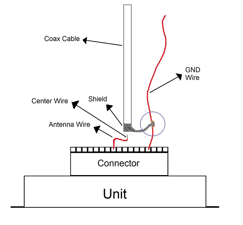
Yes, this (your picture) has high probability of succes. keeping wire lengths below 2 cm is OK. It is also OK to twist the braid into a wire so that you can connect it.
Thin 50 Ohms cable is OK (for example RG174). Because of the polyethylene dielectric in RG174, do not run it close to hot parts (PE softens at relative low temperature). If you can't avoid it, you may use teflon dielectric cable (expensive and less easy to get). If you can't get 50 Ohms cable, you may try 75 Ohms as well.
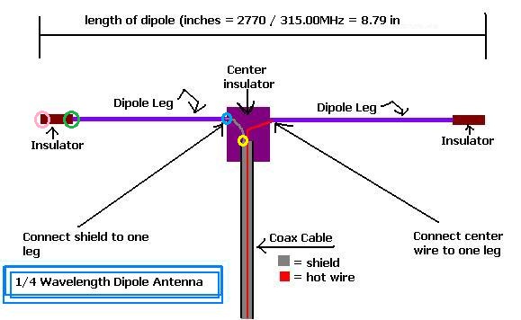
If you measured the length from the point where the cable splits into shield and center conductor, this is OK.
Where did you locate the antenna (make picture or drawing)?
If the antenna isn't the problem, the problem can be in the link budget (combination of transmitter power, distance, receiver sensitivity, noise, interference, etc). What is the actual range and what is the desired range? Is this a system where a keyfob is used to operate the alarm, or does the alarm transmit to a home-based receiver?
Best is from yellow dot to where the copper stops, If the copper stops at the pink dot, you should use distance between yellow and pink dot.
Please note that some percent change in length will not change a non-functioning solution into a well-functioning solution. So if with your dipole the range is half what you want, it will not become what you want when you change the length 1 centimeter. Antenna placement has large influence. What range do you want and what do you have now?
Some additional information may be helpful to give other tips.
Something like, 30 meters in front the car,
7 meters behind the car..
Im feel like this antenna and the previous antenna is the same range,
Now the antenna i made is in the A-Pillar,
I Tried also on the mirror(for check) and actually out the car(for check also)
Still the same,
im also tried to change the frequency in the Remote.
little helped but not that much....
its should be very good range with this antenna.....
BTW, Between the braid and the ground pin have something like 3-4 cm.
I Cant get it shorter....
its ok?
Look at the "Blue Circle" I Draw there...
I mean I cut the gnd cable, and added the shield, and i twist all the copper's together...(start gnd wire, shield, the rest gnd wire).
OK, I Cutted the dipoles from the split of the coax to the end of copper, still not that good...
I think the problem is the GND Wire, I mean its connected to the shield by 3-4cm wire.
You think this is the problem ?
And tell me if the connection of the wires is ok (From the picture I've posted before)...
This site uses cookies to help personalise content, tailor your experience and to keep you logged in if you register.
By continuing to use this site, you are consenting to our use of cookies.