Continue to Site

Welcome to EDAboard.com

Welcome to our site! EDAboard.com is an international Electronics Discussion Forum focused on EDA software, circuits, schematics, books, theory, papers, asic, pld, 8051, DSP, Network, RF, Analog Design, PCB, Service Manuals... and a whole lot more! To participate you need to register. Registration is free. Click here to register now.

A simple switch is not working in Proteus 8.15

imani9009

Newbie level 5
Joined
May 30, 2010
Messages
9
Helped
0
Reputation
0
Reaction score
0
Trophy points
1,281
Activity points
1,332
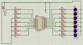
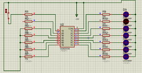
Please, any body can explain me, a simple switch is not working in proteus, whether I turn it off or on in case of R1. If I remove the switch in case of R2 then it is ok, but when I place the switch it always shows as it is on.
 

Attachments

  • water level 3.1.png
    water level 3.1.png
    50.5 KB · Views: 98
  • water level 3.png
    water level 3.png
    50.6 KB · Views: 110
Hi,

I don't know how a circuit without GND can work at all.
I know - in a simulation everything is possible ... but I don't think it makes much sense.

I guess your problem is not GND related .. still it doesn't look realistic.

Try a high ohmic pull down at the switch-ULN node.

Klaus
 
yes, I guess that GND is "invisibly" connected.

My point is this: (I'm complaining about the simulation tool)
* One does not see GND, thus it differs to a true circuit. A true circuit won't work this way at all. So for me the simulation is not realistic.
* Now when I imagine GND to be connected "invisibly" .... it has to be connected as "ideal connection" not a realistic connection. But especially hobbyists (which I guess often use this tool) are foold somehow by the simulation results.
* same is with VCC. The simulation tool treats it as "idal power supply". Not a real power supply. No need to add decoupling capacitors in this simulation. And as we often see in the forum .. people (hobbyists) don't see the need on real circuit either. Again people are fooled by the simulation results.

* and in the OP's simulation I guess it sees the ULN inputs as unrealistic high ohmic inputs ... where stray capacitance keeps a floating node at it's previous state. Again: just guessing...

So there are several points that make a simulation of such a simple circuit unrealistic .. and useless (in my eyes) ... as we can see

Klaus
 

LaTeX Commands Quick-Menu:

Similar threads

Part and Inventory Search

Welcome to EDABoard.com

Sponsor

Back
Top