Continue to Site

Welcome to EDAboard.com

Welcome to our site! EDAboard.com is an international Electronics Discussion Forum focused on EDA software, circuits, schematics, books, theory, papers, asic, pld, 8051, DSP, Network, RF, Analog Design, PCB, Service Manuals... and a whole lot more! To participate you need to register. Registration is free. Click here to register now.

A question about closed-loop stability of LDO?

Status
Not open for further replies.

ken_cn

Member level 2
Joined
Oct 9, 2005
Messages
45
Helped
5
Reputation
10
Reaction score
3
Trophy points
1,288
Activity points
1,648
opamp

Hi all,
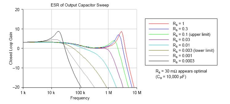
Could you tell me the reason of why the closed-loop gain has a ripple will cause the LDO unstable? Please see the Fig. which from "Stability in High Speed Linear LDO Regulator".

B.R.

Ken
 

simulation loop stability

1.) At first, the closed loop gain exhibits some "peaking" (it´s not a "ripple") indicating a stability margin which perhaps does not meet your requirements - however, the circuit "seems to be" stable !
2.) However, from this simulation alone you cannot be sure that it is stable, because at least the phase response has to be shown (therefore: "seems to be"). The problem with any simulator is, that the magnitude response as a result of an ac analysis can be fine - in spite of instability.
3.) Perform a TRAN analysis - that´s the best way to see if it works satisfying or not.
4.) If not, do a stability analysis of the open-loop function.
 

I agree with what Lvw says specially the 2nd and 3rd points.

by the way Lvw can you provide some insight on why this problem exists with the simulators...( is it becaoz they are linearizing the first solution and then calculate the ac response... where as the very next opertion point may be unstable.)

secondly how do you go for closed loop ac analysis...?
 

ashish_chauhan said:
....by the way Lvw can you provide some insight on why this problem exists with the simulators...( is it becaoz they are linearizing the first solution and then calculate the ac response... where as the very next opertion point may be unstable.)

Yes, exactly this is the reason. I don´t know if there is a simulator which - for example - indicates stability problems for ac analysis of an opamp (closed loop magnitude only) which has only positive feedback. As far as I know, the only indication for instability can in this case be derived from the phase response which shows the wrong sign.
Therefore my recommendation: Show the phase response also for closed loop analysis.
 

You did not answer my second question... was it too foolish to ask?

I have been doing only open loop simulations by opening the loop at some suitable point...
 

ashish_chauhan said:
You did not answer my second question... was it too foolish to ask?

Mmmhh - I really didn´t get the point . Did you ask me how to perform a closed loop simulation ? Was this the content of your question ?
 

If you tell that it will be helpful for me as well

thanx in advance.
 

newbiedes said:
If you tell that it will be helpful for me as well
thanx in advance.

What should I tell you ? How to perform a closed loop simulation ?
No problem: Close the loop, apply an ac signal Vin at the input and let display the expression Vout/Vin.
(Sorry for this silly answer, but what could I say more ?)
 

LvW said:
(Sorry for this silly answer, but what could I say more ?)

Don't be sorry... the question itself(asked by me ) was foolish!!!
 

Status
Not open for further replies.

Part and Inventory Search

Welcome to EDABoard.com

Sponsor

Back
Top