cmos_ajay
Full Member level 2
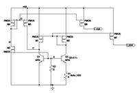
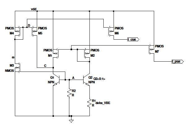
The attachment is a CTAT and PTAT current generator circuit for low voltage operation. My understanding is that as temperature increases, the Vbe(Q1) decreases and Id5 decreases since Vbe / R2 has decreases. This generates the CTAT current. Combination of the CTAT and PTAT currents makes a ZTAT current which is quite good.
However, my understanding of the role of devices M3, M4 (diode connected) and M5 is not so clear. I feel that these devices try to hold the Vcb (Q1), the collector base voltage as constant. Suppose, voltage at node A increases, then the voltage at node B decreases since M3 is like a common source device. Hence the current in M4 and M5 increases and voltage at node C increases. So the voltage at node A reduces and comes back to its original value.
Is my explanation of this feedback action correct or is there any alternative explanation ??
** This circuit is on page 425 of the book CMOS analog circuit design - Allen and Holberg (2nd edition)
")