Continue to Site

Welcome to EDAboard.com

Welcome to our site! EDAboard.com is an international Electronics Discussion Forum focused on EDA software, circuits, schematics, books, theory, papers, asic, pld, 8051, DSP, Network, RF, Analog Design, PCB, Service Manuals... and a whole lot more! To participate you need to register. Registration is free. Click here to register now.

A digital circuit which detect when inout binary number is from 9 to 19 range

Status
Not open for further replies.

aliraza786

Full Member level 4
Joined
Nov 10, 2009
Messages
210
Helped
14
Reputation
28
Reaction score
14
Trophy points
1,298
Location
Lahore, Pakistan, Pakistan
Activity points
2,914
A digital circuit which detect when input binary number is from 9 to 19 range

i wana design a circuit which can detect when the input is greater then 9 and up to 19 ......i dnt know how to use k map for five variable....can any one help me how can i use CAD tools to make such types of circuits instead of usng k map..becuse a professional approch is CAD tools..........
 

What about this breakdown step by step?

Subtract 9 from the input.

Test for value greater than or equal to zero.

If true then test for value less than or equal to 10.
 

What about this breakdown step by step?

Subtract 9 from the input.

Test for value greater than or equal to zero.

If true then test for value less than or equal to 10.

Doesn't that complicate things since now signed/unsigned numbers are introduced? (i.e. if input < 9 to start with, the tested value will be negative)
 

Re: A digital circuit which detect when input binary number is from 9 to 19 range

i wana design a circuit which can detect when the input is greater then 9 and up to 19 ......i dnt know how to use k map for five variable....can any one help me how can i use CAD tools to make such types of circuits instead of usng k map..becuse a professional approch is CAD tools..........
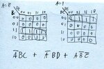
K-mapping 5 variables isn't that bad... just make two 4x4 maps... one for A=0 and one for A=1.
k-map.jpgtable.PNG

This one doesn't give you an opportunity to optimize the equation specifically for a five variable design-space. Notice the groupings of four? Well, you can also make groupings back "stacking" the A=0 and A=1 cases on top of one another. The groupings of 2/4/8/16 one's would then extend across the layers. This example doesn't have any of those, so I'll give you a simple one.

Say you also wanted Out to go high from 0-3 (the top row of A=0 would also be 1,1,1,1), then you could simplify the equation and make it /ABC + /ABD + /B/C, since you'd have 1,1,1,1 on layer A=0 sitting directly on top of 1,1,1,1 on layer A=1, which would make a group of 8 ones.
 

Doesn't that complicate things since now signed/unsigned numbers are introduced?

I didn't know whether you wish to leave the input value unchanged.

My recall of the command set for using registers is rusty. I had the idea that since my algorithm doesn't use the command to test for less than zero, then it didn't involve signed binary.

I also wasn't sure if you wanted to use hardware or code in the final project. It will get pretty involved if you use IC's to compare a value with 9, then with 19.

I was trying to think of a way that requires fewer IC's. I guess my suggestion didn't simplify much.
 

Status
Not open for further replies.

Part and Inventory Search

Welcome to EDABoard.com

Sponsor

Back
Top