Continue to Site

Welcome to EDAboard.com

Welcome to our site! EDAboard.com is an international Electronics Discussion Forum focused on EDA software, circuits, schematics, books, theory, papers, asic, pld, 8051, DSP, Network, RF, Analog Design, PCB, Service Manuals... and a whole lot more! To participate you need to register. Registration is free. Click here to register now.

877a and 4x20 LCD dark squares..

Status
Not open for further replies.

jungardc2

Newbie level 5
Joined
Feb 16, 2010
Messages
9
Helped
0
Reputation
0
Reaction score
0
Trophy points
1,281
Location
Philippines
Activity points
1,348
hi masters..
b4 i got a program with a pic16f628a with a 4x20 LCD and it did work..
but when i switch to an pic16f877a..all i have are dark squares..

my program is in pic basic..
changes i added wd the pic includes having a 4mHz xtal, pull up resistor in MCLR to +5v and nothn more..

now..i ask the masters for help..
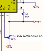
 

May your problem be about the contrast? The squares you mentioned, generally appears about it at 2x16 LCD.

58_1271407198.jpg
[/img]
 

sir..i got a contrast control d same wen i was programmn wd d pic16f628a..and stil it is wd d 877a..

so i thnk it is not the problem..
 

the dark squares mean the LCD is not being setup correctly, and that either the PIC is not sending the setup routine or the PIC is sending them too fast.

Try reducing the clock pulses to the LCD, and can you use a scope and see if the PIC is sending anything at all.

Finally ensure the connection are OK and also check the code and see if the pins are correctly configured.
 

1. how to reduce clock pulses?
my clock frequencly wd my program is 4mHz and i used 4mHz xtal wd the 877a.

2. scope? im workn at home and i got no scope..

3. connections are checked..many times..

4. code? it is correct when i simulate it in the PIC Simulator
 

I come across that problem, when contrast isn't correct and when the LCD is broken down. If your circuit with 16f628 still exists, you can connect the LCD to that circuit to test the LCD. Also the problem may be at the power connections of the LCD, because you don't need to connect the power connections at the proteus simulation(if you use proteus for simulation of course).
Note: My suggestion are made over the 2x16 LCD.
good luck.
 

By clock frequency I meant the rate at which the enable pin of the LCD is pulsed.

As you may be aware the enable pin of the LCD needs to be toggled (high to low) whenever data has to be sent to the LCD, if this toggling is fast then the LCD module may not be able to capture the data presented to it. So try slowing it down, increase the time for which the enable pin is high.

Are you trying this on a simulator ?? or an actual hardware ??

Are you sure contrast pin is connected correctly.
 

but when i switch to an pic16f877a..all i have are dark squares..

USING SMS LANGUAGE/SHORT HAND TYPING IS NOT ALLOWED HERE.

Did you get dark squares in all four lines or in the first line?

If you get it in the first line only, then there is initialization problem. If you are getting it in all four lines then the problem lies in the contrast setting

Nandhu
 

oh i got the problem or in our language..the problema!

i bought new PIC and it got worked.
thanks to you all of my masters and for the ideas..
i dont know why my old 877a is deffective in a way that it s readable and programmable but nevermind..i got my project working!
 

hi!
as u told that dark square problem is due to ,
the lcd contrast adjustment

if you are not connected a contrast adjustment for the LCD ,

connect a 10K pot to LCD and by adjusting pot you can get the best results............

pin no: 3 of LCD to POT center pin

one pin is connected to VCC and another to ground.

i think it will work.
 

read the post above, the OP solved the problem by replacing the PIC.
 

Hello all,
hope u r all doing well
I have the same problem, and I use the same PIC you are talking about, and I have the same problem :(
My problem is that I wrote a sample code to connect the LCD and it worked, but when I modified the code a little bit, all I got is dark squares knowing that I tried the code on protus PIC simulator and it works !!!!!!
Can you help me please :)
thank you in advanced
 

Status
Not open for further replies.

Similar threads

Part and Inventory Search

Welcome to EDABoard.com

Sponsor

Back
Top