Continue to Site

Welcome to EDAboard.com

Welcome to our site! EDAboard.com is an international Electronics Discussion Forum focused on EDA software, circuits, schematics, books, theory, papers, asic, pld, 8051, DSP, Network, RF, Analog Design, PCB, Service Manuals... and a whole lot more! To participate you need to register. Registration is free. Click here to register now.

8086 connection to eprom - problem

Freddy flint

Newbie level 5
Joined
Sep 28, 2023
Messages
9
Helped
0
Reputation
0
Reaction score
0
Trophy points
1
Activity points
127
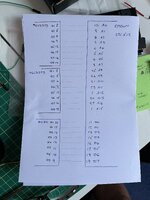
I’m trying to connect an eprom containino 3 simple lines of machine code as a test. The code is mov ax, 45
add ax, 7
mov [6000], ax
I have two 8 bit 512 eproms, as the 8086 reads 16 bits of data and eproms have 16 address lines and 8 data lines
The 16 address lines connect to both eproms a0 to a15 inputs via two 74ls373 latches
On one eprom I have d0 to d7 data lines and on other d8 to d15, to allow 16 bits to be read. The two eproms have the machine code loaded identically, and idea is the 8086 will read the 16 bits as one read. On reset the cpu sets the address to FFFFO so I have the code in eprom loaded at FFF0 to FFFA. On reset the address presented to the 2 eproms via the latches is FFF0. But I’ve hit a problem as I have the two eproms connected to the address with eprom chip enable held low and chip select connected to the read output of cpu. But both eproms have address FFF0. So do I connect A0 of the 2nd eprom high, so that first address on eprom one is FFF0 and other EPROM address is FFF1, on the next cycle the instruction pointer moves to FFF2 but as I have 2nd eprom with a0 address held high it should have FFF3 ? Is that how it works and how the cpu can read 16 bits with 8 from one and 8 from 2nd, or is it more complex ?
 
Its a bit confusing to read but as I understand it you have two eproms and you are latching the address bus which is then fed to both of them in parallel. That means whatever address you select and latch will be common to both eproms but you want to access them at different addresses. I think what you are asking for is to read the high 8-bits and low 8-bits at adjacent addresses. If I'm right, you need to use A0 to select one of two data latches, not address latches. Basically selecting the data from one or the other eprom at alternating addresses.

Brian.
 
You are missing basic information of x86 bus operation. They are answered in 8086 user manual and circuit examples.
For 8-bit read-only devices, you simply connect bus A[16..1] to memory A[15..0]. x86 16 bit data bus is expecting the respective data at D[15..8] respectively D[7..0], independent of A0 state. 8 bit writes need to process A0 additionally.
 
Its a bit confusing to read but as I understand it you have two eproms and you are latching the address bus which is then fed to both of them in parallel. That means whatever address you select and latch will be common to both eproms but you want to access them at different addresses. I think what you are asking for is to read the high 8-bits and low 8-bits at adjacent addresses. If I'm right, you need to use A0 to select one of two data latches, not address latches. Basically selecting the data from one or the other eprom at alternating addresses.

Brian.
Hi Brian
Yes, that’s it exactly. Both EPROMs have identical machine code loaded. Both EPROMs are connected to the 16 address output of the address latch a0 to a15. Eprom 1 is connected to data lines d0 to d7 and eprom 2 is connected to data lines d8 to d15. So yes the idea is the 8086 reads 16 bits so it will read low byte from eprom 1 and high byte from eprom 2
But as both are connected in parallel to the address latch they both have identical addresses. I realised eprom 1 should have even address and eprom 2 the odd address. So on reset of cpu the address is FFF0 but both EPROMs are getting address FFF0 where eprom 1 should get FFF0 and eprom 2 FFF1
I don’t have any data latches ?
As the address and data lines from the 8086 are multiplexed I just added latches to the address to hold the address with idea when 8086 switches to data I can just connect the data lines to the eprom
So you say I need to add additional logic to latch the data lines ? Can I not just on eprom 2 invert the A0 connection so it’s a 1 ?
So when address is FFF0 on eprom1 it’s FFF1 on eprom 2. Then when the cpu on next cycle goes to FFF2 as I have inverted A0 to eprom 2 it has FFF3 ?
--- Updated ---

Hi,

Please show a schematic. Hand drawn is O.K.

Klaus
Hi,

Please show a schematic. Hand drawn is O.K.

Klaus
Hi Klaus
Thanks for your help
Attached is the connection of eprom 1 to the address latches and to the lower data lines from the 8086 do to d7
The other eprom is connected identically to the address latches but the 8086 data lines d8 to d15 connect to it
Both EPROMs have identical machine code
The idea is the 8086 will read 16 bits of data the low byte from eprom 1 and high byte from eprom 2
But as the address lines are identical and connected in parallel I realised both EPROMs are receiving the same address
So can I just invert the a0 address connection to eprom 2 ?
So on reset when 8086 sets address to FFF0 eprom 1 gets address FFF0 and as I have inverted a0 to eprom 2 it gets FFF1
Then when on next cycle it goes to FFF2 eprom 2 will get FFF3
I have 2 other signals on both my 27c512 eprom that of CE and OE , both are active low
I currently have chip enable held low and OE connected to read output from 8086
To me inverting a0 line to eprom 2 should work provided 8086 reads 16 bits in the one read cycle with low byte from eprom 1 and high from eprom 2
--- Updated ---

You are missing basic information of x86 bus operation. They are answered in 8086 user manual and circuit examples.
For 8-bit read-only devices, you simply connect bus A[16..1] to memory A[15..0]. x86 16 bit data bus is expecting the respective data at D[15..8] respectively D[7..0], independent of A0 state. 8 bit writes need to process A0 additionally.
Thanks so much for your reply. Yes I did consult the 8086 manual but found it confusing
I realised data and address are multiplexed
So added latches to capture address
I have eprom 1 and eprom 2 connected to address lines a0 to a15 from address latch
Then eprom 1 to data lines d0 to d7 and eprom 2 to d8 to d15
Both EPROMs have identical code
The EPROMs are 27c512 so have 16 address lines and 8 data lines
I want to read 16 bits with low byte from eprom 1 and high byte from eprom 2
So my thought was to invert a0 address from address latch only to eprom 2
So on reset the address is FFF0 on eprom 1 and FFF1 on eprom 2 as I inverted A0 to eprom 2
Then on next address output by 8086 of FFF2 it will place FFF3 on eprom 2
But will that work ?
 

Attachments

  • IMG_9559.jpeg
    IMG_9559.jpeg
    1.9 MB · Views: 70
Last edited:
FvM's post #4 agrees with my experience from other processors. You don't connect the processor A0 to the memories at all. The processor A1 is connected to A0 on the memories, A2 to A1, etc.
The A0 processing is done internally in the processor, to use the low or high byte of the external data bus.
 
Hi,

Attached is the connection of eprom
This can´t replace a schematic. There is so much information missing.

So can I just invert the a0 address connection to eprom 2 ?
I´v never used 8086. I did a serach on "8086 16 bit memory schematic" and found good information on the first hit.
You could do the same. Or do like the other posters recommended.
To your question: No. A0 can´t be used for this. It is done via BLE and BHE.

*****
But: Why using a 45 years old microcontroller, outdated, slow, complicated to wire, high power consumption, with bad availability at all?

Every modern 16 bit microcontroller (indeed most 8 bit modern microcontrollers) will beat this guy in every manner.
Usually they have built in RAM, ROM, address decoder - so no external wiring needed for this. Are in system programmable (don´t need high quality EEPROM sockets and don´t need an eternity to delete/reprogram the EEPROM). Have a lot of built in periferals.

Klaus
 
Hi,


This can´t replace a schematic. There is so much information missing.


I´v never used 8086. I did a serach on "8086 16 bit memory schematic" and found good information on the first hit.
You could do the same. Or do like the other posters recommended.
To your question: No. A0 can´t be used for this. It is done via BLE and BHE.

*****
But: Why using a 45 years old microcontroller, outdated, slow, complicated to wire, high power consumption, with bad availability at all?

Every modern 16 bit microcontroller (indeed most 8 bit modern microcontrollers) will beat this guy in every manner.
Usually they have built in RAM, ROM, address decoder - so no external wiring needed for this. Are in system programmable (don´t need high quality EEPROM sockets and don´t need an eternity to delete/reprogram the EEPROM). Have a lot of built in periferals.

Klaus
Thanks so much Klaus,
Why 8086 ? - because back in 1983 I was a programmer for marconi radar systems . I wrote the air traffic control software for Marconi using assembler and it was used for all the UK air traffic controllers. The hardware guys built the computer using an 8086 then gave me the memory map of the address of RAM and ROM and Display etc etc . I had nothing to do with the hardware but now I’m retired and the components are cheap I wanted to try and build an 8086 on a breadboard. I wanted to write a very very simple machine code and load that into eprom and run it. It was simple with 8080 as its 8 bit. I just connected the address lines to latches and then to eprom and 8 data lines to eprom
But on 8086 I ran into issues. Hence my question
i did do as you suggested search 8086 16 bit memory schematic but just got confused. Yes it talks about A0 and BLE and BHE but I couldn’t figure it out al all, hence the post
To me, the 8086 has 16 bit data bus
On reset of the 8086 it starts at address FFFF0, then it goes to FFFF2 then to FFFF4
So if I had a 16 x 16 eprom I connect latch addresses and data adresses
but I only have two 16x8 eproms
so I thought connect 16 address lines from latch to both EPROMs and the low data lines to eprom 1 and high to eprom 2
So now to the 8086 it thinks it’s got 16x16 eprom
but I got confused on reading the schematics and low byte in low eprom and high byte in high eprom
I’d have to create a binary file then split that into high and low bytes, but how would that work ? If only the low bytes of machine code were in low eprom and high bytes in high eprom how could 8086 address that ?
The 8086 puts out on its 16 address lines FFF0 FFF1
so eprom 1 has at address FFF0 the first byte machine code, the 2nd eprom can’t have the same machine code instruction at FFF0 ! Surely the 2nd eprom must have its instruction at location FFF1 in the eprom. This must mean the location FFF0 in eprom 2 is empty ?
so I got very confused, and decided to post and ask the question how do I do this ?
 
Here's the ROM connection scheme from Intel 80186 user manual. It's also expected that 16 bit data are split into odd and even address data and programmed to both EPROMs respectively.

1695983217668.png
 
That's wrong. One EPROM must hold high byte and other low byte of 16 bit data. EPROM programmers have functions to split 16 bit data file into two 8 bit images.
Thanks FvM
i really really appreciate the response. I’ve confused myself I think
yes, I see what you say BUT ?
and this is why I posted on here to get advice
My thoughts were exactly that
i created a binary file and then split it into low and high bytes
i then uploaded the low bytes to eprom 1 and high to eprom 2
so the binary code is this
B8 93 00 83 CO 05 A3 00 60
this is little Indian so address 6000hex is written 00 60
The mov ax, 93hex is B8 as the mov instruction
So in creating this binary file at the location FFF0 then FFF1 then FFF2 I would have this
FFF0 B8
FFF1 93
FFF2 00
FFF3 83
FFF4 C0
etc etc

if I then split this so low bytes are in eprom 1 and high in eprom 2 I will have this
eprom 1 - B8 00 C0 etc
eprom 2 - 93 83 etc

so the low bytes in eprom 1 and high bytes in eprom 2

but when I came to try and upload that via my eprom programmer I get
eprom 1
address FFF0 B8
address FFF1 00
address FFF2 C0
etc

eprom 2
address FFF0 93
address FFF1 83

so that’s when I though, Ah ok I do have to connect the 16 address lines from the latches to the EPROMs in exactly the same way
so eprom 1 gets address FFF0 and eprom 2 gets address FFF0

but then I thought “hold on could I not fool the 8086 into reading 16 bits without having to split the EPROMs. If I load the code identically into both and just set the 2nd eprom to get the odd address would that not work

Then I saw all this stuff on A0 and BHE and got so confused, so thought id post “how the heck do I create a circuit just to read 2 8 bit EPROMs“
--- Updated ---

Here's the ROM connection scheme from Intel 80186 user manual. It's also expected that 16 bit data are split into odd and even address data and programmed to both EPROMs respectively.

View attachment 185191
thats What I thought
the 8086 is reading 16 bits
but it’s presenting an address of (in diagram above) 15 bits
so 7FF0. It doesn’t use A0 or BHE which is fine
BUT an 8086 on reset sets instruction pointer to FFFF0
so if you take the address lines a0 to a14 that’s 7FF0
so it’s presenting to eprom 1 address 7FF0
and to eprom 2 address 7FF0
if I have only low byte part in eprom 1 and high byte in eprom 2
and both at address 7FF0 in eprom 1 & 2
then all is ok
BUT the next address the 8086 presents is FFF2 not FFF1 and that’s whats confused me
 
Last edited:
A0 is not connected to the EPROMs, so the addresses 0xfff0 and 0xfff1 will be 0x7ff8 locally to both of them. The 8086 uses A0 internally to select the low or high byte (only necessary for 8-bit transfers).
 
A0 is not connected to the EPROMs, so the addresses 0xfff0 and 0xfff1 will be 0x7ff8 locally to both of them. The 8086 uses A0 internally to select the low or high byte (only necessary for 8-bit transfers).
Ok
thank you very much

that makes sense. I saw that the instruction pointer on the 8086 moves in twos. So it starts at FFFF0 then FFFF2 then FFFF4
so my assumption was this is because it’s reading 2 bytes of data at a time
So for my 27C512 eprom that has 16 address lines and 8 data lines
With the 16 address lines connected via the latch it’s seeing FFF0
Then on next cycle it’s FFF2
This allows 8086 to read 2 bytes of data at a time
Hence my question (although badly expressed) was is it ok to present the same address to both EPROMs
I gather that the answer is yes, as the 8086 is not bothering with the A0 line as it just reads 2 bytes as it’s reading 16 bits at a time with d0 to d7 on one eprom and d8 to d15 on the other

This means I have to split my machine code into 2 halves
with lower byte in eprom 1 and higher byte in eprom 2
my eprom is a 512 so it’s address on programming the eprom runs from 0000 to FFFF

So in eprom 1 I load the lower byte at what address in the eprom ? Is it at address FFF0 ? Then in eprom 2 the high byte do I load the high byte instruction at address FFF0 in the eprom too ?

so as an example the mov ax, 93hex machine code is, in little endian
B8 93 00

So do I put at location FFF0 in low byte eprom B9 and at FFF1 00
and in eprom 2 the high byte I put at FFF0 address in the eprom 00 ?

If that’s the case, on the next instruction pointer of FFF2 put out by the 8086 it will not read from the low eprom the machine code 00 as the low eprom has this at location FFF1 ?

Thats my problem. I can’t see how to set the addresses in connecting to the eprom and then the correlation to the addreees in the eprom where the machine code is.
 
Two 27512 can hold 128 kB of data if you have A16 available in your bus. Reset address ist actually 0xFFFF0 in 1 MB memory map. Code EPROM base address depends on how you decode upper address lines.

If don't use A16 and cut code memory to 64 kB, EPROM A15 has to be connected either to L or H level, reset address will be 0x7ff0 or 0xfff0 either.

This is however very basic x86 system design stuff and discussed in many documents.
 
so as an example the mov ax, 93hex machine code is, in little endian
B8 93 00

So do I put at location FFF0 in low byte eprom B9 and at FFF1 00
and in eprom 2 the high byte I put at FFF0 address in the eprom 00 ?

B8 must be at address 0x7ff8 in the low byte EPROM, and 93 must be at address 0x7ff8 in the high-byte EPROM. When the 8086 goes to address 0xfff2 (and 0xfff3) the EPROMs will see address 0x7ff9.
Remember, A1 from the 8086 is connected to A0 of the EPROMs. A0 from the 8086 is not connected.
 
Thanks FvM
Yes, I’ve used some logic to set the Eprom using the chip enable on the EPROMs to set a memory map as you indicate
I’m using the A15 line so that the EPROM is only addressable from 8000 to FFFF
As you indicate this is basic design stuff and documented well

It does mean I’m doing this there is a trade off as I don’t have then access to the full eprom capacity. But memory space isn’t an issue

My plan was to add an LCD display and add that at address 6000hex and then to add RAM at address 4000hex and I have the additional logic to do that to provide the memory map

However I hadn’t got to that stage and had fallen at the first hurdle of just adding the code into the eprom

The chip enable on the EPROMs is connected so it’s only addressed from 8000 to FFFF

But to check it was functioning before I went further I just wanted to add some code to the eprom. As you say it seemed a basic 8086 design stuff, but I got stuck on how do you actually load in the machine code at the correct eprom address

I haven’t been able to find an answer to this. Certainly there are lots and lots of resources out there saying how to physically connect the 8086 to the eprom and that the eprom has to be split high and low but nothing on exactly what machine code byte goes in what eprom address, hence my reach out to this board to request, how is this actually achieved
 
B8 must be at address 0x7ff8 in the low byte EPROM, and 93 must be at address 0x7ff8 in the high-byte EPROM. When the 8086 goes to address 0xfff2 (and 0xfff3) the EPROMs will see address 0x7ff9.
Remember, A1 from the 8086 is connected to A0 of the EPROMs. A0 from the 8086 is not connected.
Ah . I get it - thank you
Of course if a0 isn’t connected to EPROMs
Then address they will see is 7FF8
thanks
 

LaTeX Commands Quick-Menu:

Part and Inventory Search

Welcome to EDABoard.com

Sponsor

Back
Top