techie
Advanced Member level 3
It is strange that the LCD is causing a drop in voltage. If the 8051 pins are left open or are connected to a CMOS input, it should show close to 5V. Can you check with oscilloscope to see what is happening.
Follow along with the video below to see how to install our site as a web app on your home screen.
Note: This feature may not be available in some browsers.
What is the voltage before connect AT89S51 to LCD module?1.8V is measured after it is connected to LCD.
budhy said:What is the voltage before connect AT89S51 to LCD module?1.8V is measured after it is connected to LCD.
techie said:I think what is happening here is that the LCD port is being written at a high speed and the multimeter is showing the average voltage of the port pin which is actually 0-5V pulses.
That's the answer, there is some problem with your 8051 chip or some thing wrong with your PCB circuitry.It is also around 1.8V, very weird.What is the voltage before connect AT89S51 to LCD module?
It is strange that the LCD is causing a drop in voltage.
Please measure the voltage at pin #20 & #40 of 8051! (that is power supply pins)
  ORG 0000H     ;Power up
  SJMP MAIN

  ORG 50H
MAIN:
  MOV   P2,#01H
  ACALL DELAY
  MOV   SCON,#52H     ;8-bit, 1 stop bit, REN enabled
  MOV   TMOD,#20H     ;Timer 1 in mode 2
  MOV   TH1,#-3       ;9600 baud rate
  SETB  TR1           ;Start timer 1
  MOV   DPTR,#ST      ;Get address of Station
  MOV   R6,DPH        ;Save higher data pointer
  MOV   R7,DPL        ;Save lower data pointer
  SETB  P3.0
  SETB  P3.1
  MOV   P2,#81H
  ACALL DELAY
NextMessage:
  MOV   DPTR,#AT      ;Get address of AT
  MOV   P2,#11H
  ACALL DELAY
  ACALL SingleCommand ;Send AT+CMGF
  MOV   DPTR,#CMGF    ;Get address of AT+CMGF
  MOV   P2,#22H
  ACALL DELAY
  ACALL SingleCommand ;Send AT+CMGF
  MOV   DPTR,#CSCA    ;Get address of AT+CSCA
  MOV   P2,#33H
  ACALL DELAY
  ACALL SingleCommand ;Send AT+CSCA
  MOV   DPTR,#CMGS    ;Get address of AT+CMGS
  MOV   P2,#44H
  ACALL DELAY
  ACALL ATcommand   ;Send AT+CMGS

WaitReady:
  ACALL SerialIn    ;Get the status of the phone
  CJNE  A,#'>',WaitReady ;Repeat if symbol '>' not received

  MOV   DPH,R6      ;Retrieve higher address of station
  MOV   DPL,R7      ;Retrieve lower address of station
  ACALL ATcommand   ;Send station
  MOV   R6,DPH      ;Save current higher address of station
  MOV   R7,DPL      ;Save current lower address of station
  CLR   A           ;Clear accumulator
  MOVC  A,@A+DPTR   ;Get data to be saved into accumulator
  JNZ   NextMessage ;Jump to NextMessage if '0' is reached
  MOV   P2,#88H
  ACALL DELAY
FINISH:
  JMP   FINISH      ;If yes, end of program

SerialOut:
  MOV   SBUF,A      ;Load the data
WaitTI:
  JNB   TI,WaitTI   ;Stay until last bit sent
  CLR   TI          ;Get ready for next character
  MOV   P2,#55H
  ACALL DELAY
  RET

SendIt:
  ACALL SerialOut   ;Jump to send
ATcommand:
  CLR   A           ;Clear accumulator
  MOVC  A,@A+DPTR   ;Get data to be saved into accumulator
  INC   DPTR        ;Point to next data
  MOV   P2,#99H
  ACALL DELAY
  JNZ   SendIt      ;Jump to send if it is not zero
  RET

SingleCommand:
  ACALL ATcommand   ;Jump to ATcommand
Wait0DH:
  ACALL SerialIn    ;Jump to receive
  CJNE  A,#0DH,Wait0DH ;Jump if not equals to carriage return
  MOV   P2,#77H
  ACALL DELAY
  RET

SerialIn:
  JNB   RI,SerialIn ;Wait for another character
  MOV   A,SBUF      ;Save it in accumulator
  CLR   RI          ;Get ready for next character
  MOV   P2,#66H
  ACALL DELAY
  RET

DELAY:
  ACALL DELAY1
  ACALL DELAY1
DELAY1:
  MOV   R2,#0FFH  ; 1 machine cycle,1.085us
LONG1:
  MOV   R3,#0FFH  ; 1 machine cycle,1.085us
LONG2:
  DJNZ  R3,LONG2  ; 2 machine cycle .
  DJNZ  R2,LONG1  ; Total delay = 256X256X2X1.085u = 142ms
  RET

AT:     DB 'AT',0DH,0
CMGF:   DB 'AT+CMGF=1',0DH,0
CSCA:   DB 'AT+CSCA="+60120000015"',0DH,0
CMGS:   DB 'AT+CMGS="+60122521131"',0DH,0
ST:     DB '01',0,'02',0,'03',0,0
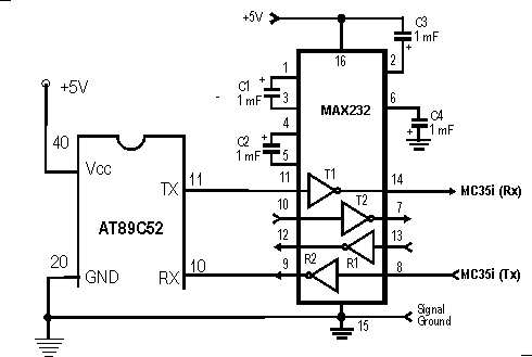
ENDafter that :Then I tried to use Siemens MC35i terminal, with this, the program doesn't even run, and the voltage on P3.1 which is transmission port is -0.63V, why does this happen? For this GSM module, I need to just connect the Txd, Rxd and Gnd only right? Any other pins to be connected?
How do you connect Siemens MC35i terminal to MCS51? Directly?Too bad my 8951 chip is not functioning now, even a simplest program also it doesn't run, it is so weird that I haven't touched it after I've finished trying yesterday, yet it doesn't work at all when I tried today...
what do you mean with interfacing Nokia mobiles with a cell phone?Can any one please give me a schematic about interfacing Nokia mobiles with a cell phone?
Do you realize that Siemens MC35i terminal connector is RS232 signal which operate on -12 to +12 Volt? Siemens MC35i terminal will burn out you uC chip if you connect them directly!
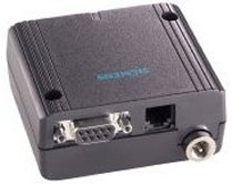
is this the Siemens MC35i that you mean?Then how shall I connect this Siemens MC35i to 8951?
Can any one please give me a schematic about interfacing Nokia mobiles with a cell phone?
Basically the µC-Cellphone interface circuit is a serial interface circuit only, connect µC RX to cellphone TX dan connect cellphone RX to µC TX, but you have to consider the voltage level different between them!I want the microcontroller to command a Nokia phone, to send SMS, or call a particular number, or fetch a new SMS from the mobile