Continue to Site

Welcome to EDAboard.com

Welcome to our site! EDAboard.com is an international Electronics Discussion Forum focused on EDA software, circuits, schematics, books, theory, papers, asic, pld, 8051, DSP, Network, RF, Analog Design, PCB, Service Manuals... and a whole lot more! To participate you need to register. Registration is free. Click here to register now.

[SOLVED] # 8051 and adc 0804 simulation in proteus problem.

Status
Not open for further replies.

anj

Member level 3
Joined
Aug 16, 2012
Messages
66
Helped
7
Reputation
14
Reaction score
7
Trophy points
1,288
Location
Rajkot, Gujarat, India
Activity points
1,679
hello..
I have weird problem.. when I am simulating adc 0804 with 8051 mc in proteus and displaying on lcd then it gives correct simulation..
but as soon i palce an another adc to convert other input to digital then it stops working..
does anybody knows about this issue?? :???:
 

thank you for replying jayanth.. :smile:

but this is kind a "out of syllabus" problem..
I want to simulate two ADC with 8051 (in proteus AT89C52) since there is no practical purpose of this project.
otherwise I know that there are many controller IC's with inbuilt ADC and also multiple channels as you have said.
 

sure.. :)
Code:
#include <regx51.H>
//#include <serial_s.H>
#include<math.h>
#include<stdio.h>
#include<lcd.h>

#define adc_port1 P0              //ADC Port
#define adc_port2 P2
 
sbit rd1 =  P1^0;                //Read signal P1.0
sbit wr1 =  P1^1;               //Write signal P1.1
sbit cs1 =  P1^2;                //Chip Select P1.2
sbit intr1= P1^3;             //INTR signal P1.3

sbit rd2 =  P1^4;                //Read signal P1.0
sbit wr2 =  P1^5;               //Write signal P1.1
sbit cs2 =  P1^6;                //Chip Select P1.2
sbit intr2= P1^7;             //INTR signal P1.3

void conv(int);                     //Start of conversion function
void read(int);                     //Read ADC function
void msdelay(int);
void maths1();
void maths2();
unsigned char adc_val;
float val;
int temp ;
void main()
{
		//serial_init();
		lcd_init();
		lcd_clear();
        while(1)
		{                    
                conv(1);                  //Start conversion
                read(1);                  //Read ADC        
				maths1();
				msdelay(1000);

//                conv(2);                  //Start conversion
//                read(2);                  //Read ADC        
//				maths2();
//				msdelay(1000);


        }
}

void conv(int j)
{		
	if(j==1)
{
        cs1 = 0;                      //Make CS low
        wr1 = 0;                      //Make WR low
        wr1 = 1;                      //Make WR high
        cs1 = 1;                      //Make CS high
        while(intr1);                 //Wait for INTR to go low
}
else
{
		cs2 = 0;                      //Make CS low
        wr2 = 0;                      //Make WR low
        wr2 = 1;                      //Make WR high
        cs2 = 1;                      //Make CS high
        while(intr2);                 //Wait for INTR to go low
}

}

void read(int j)
{

		if(j==1)
	{
        cs1 = 0;                      //Make CS low
        rd1 = 0;                      //Make RD low
        adc_val = adc_port1;          //Read ADC port
        rd1 = 1;                      //Make RD high
        cs1 = 1;                      //Make CS high
	}

 	else
	
	{
	    cs2 = 0;                      //Make CS low
        rd2 = 0;                      //Make RD low
        adc_val = adc_port2;          //Read ADC port
        rd2 = 1;                      //Make RD high
        cs2 = 1;                      //Make CS high
	
	}

}


void maths1()
{
 				
				lcd_line1("voltage: ");
				val=(float)adc_val/51;
				temp =(int)val;
				lcd_data(temp+0x30);
				val=val-temp;
				lcd_data('.');
				val=val*10;
				temp=(int)val;
	            lcd_data(temp+0x30);
				val=val-temp;
				val=val*10;
				temp=(int)val;
				lcd_data(temp+0x30);

}


void maths2()
{
 				
				lcd_line2("current: ");
				val=(float)adc_val/51;
				temp =(int)val;
				lcd_data(temp+0x30);
				val=val-temp;
				lcd_data('.');
				val=val*10;
				temp=(int)val;
	            lcd_data(temp+0x30);
				val=val-temp;
				val=val*10;
				temp=(int)val;
				lcd_data(temp+0x30);

}


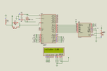
this code works perfectly with single ADC..
 

a.png

see this snap.

- - - Updated - - -

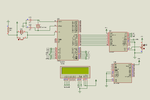
b.png

now see this just another ADC and LCD is blank... :shock:
 

Whare is the CS2, RD2, WR2, DB0-DB7, INTR, Vin+ connection to the second ADC0804? zip and post your keil project files and proteus file. I will fix it in 5 minutes.
 
Last edited:

The problem is if you interface bothe ADC outputs to same input port P2 of MCU then even if one ADC is selected the previous data of other adc is placed on P2 also. So, you will get wrong value. If ADC 1 is selected and ADC 2 is not selected in the second conversion routine, ADC 2 still have the previous conversion data on its output and If you connect both ADC o/ps to P2 then the new data of ADC1 and old data of ADC2 will clash on the bus of P2.
 

try This and chang code acoding ADC0804
 

Attachments

  • ADC.zip
    22.3 KB · Views: 109

The problem is if you interface bothe ADC outputs to same input port P2 of MCU then even if one ADC is selected the previous data of other adc is placed on P2 also. So, you will get wrong value. If ADC 1 is selected and ADC 2 is not selected in the second conversion routine, ADC 2 still have the previous conversion data on its output and If you connect both ADC o/ps to P2 then the new data of ADC1 and old data of ADC2 will clash on the bus of P2.

Hello jayanth..
I have already used different ports for taking ADC outputs i.e. PORT0 and PORT2 still problem persists..
 

Post your project files and Proteus file and I will fix it in 1 hour. I think you have not used pull-ups on P0. P0 is open collector outputs and need pull-ups to work as digital I/O pins.
 

try This and chang code acoding ADC0804

thanks arun .. :smile:
coding works fine but its problem of simulating two ADC's 0804..
no doubt 0808 will suffice the needs...

- - - Updated - - -

Post your project files and Proteus file and I will fix it in 1 hour. I think you have not used pull-ups on P0. P0 is open collector outputs and need pull-ups to work as digital I/O pins.
I've posted one zip file in post #9.. that's all I have.. nothing like a big project but want to simulate two 0804 ADC :idea:
 

Attachments

  • 2_0804.rar
    84.7 KB · Views: 120
Last edited:
  • Like
Reactions: anj

    anj

    Points: 2
    Helpful Answer Positive Rating
Thanks jayanth.. :smile:
this is kind a software bug problem..
since there is no question of hardware implementation so we can close this thread.. thanks again.. :smile:
 

Status
Not open for further replies.

Similar threads

Part and Inventory Search

Welcome to EDABoard.com

Sponsor

Back
Top