engwas
Member level 1
dear SunnySkyguy
i notice that same problem not on 7 segment and multiplexing it take very small time the problem in fetch data from ds1307 i make it fetch every 1 minute it blink at that moment
so how to fix it
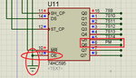
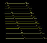
the multiplexing as below

Thanks
- - - Updated - - -
Dear
i measure the time of get data from the ds1307 it only 3.28 ms as the function Get_DS1307_RTC_Info();
kindly need any help
- - - Updated - - -
Dear I think the blink from my pc sometimes happen and sometimes not so i attached the circuit kindly if anyone try it and tell me it blink or not
and i need solution for the led that indicate the PM time
Thanks
i notice that same problem not on 7 segment and multiplexing it take very small time the problem in fetch data from ds1307 i make it fetch every 1 minute it blink at that moment
so how to fix it
the multiplexing as below
Thanks
- - - Updated - - -
Dear
i measure the time of get data from the ds1307 it only 3.28 ms as the function Get_DS1307_RTC_Info();
kindly need any help
- - - Updated - - -
Dear I think the blink from my pc sometimes happen and sometimes not so i attached the circuit kindly if anyone try it and tell me it blink or not
and i need solution for the led that indicate the PM time
Thanks
Attachments
Last edited: