Continue to Site

Welcome to EDAboard.com

Welcome to our site! EDAboard.com is an international Electronics Discussion Forum focused on EDA software, circuits, schematics, books, theory, papers, asic, pld, 8051, DSP, Network, RF, Analog Design, PCB, Service Manuals... and a whole lot more! To participate you need to register. Registration is free. Click here to register now.

6v-12v AC/DC to 5v regulated DC <100mA, the easy way?

Status
Not open for further replies.
It would have to be a 'real' transformer so probably too big to fit in the tube base.
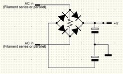
An alternative idea along the same lines might be to use a bridge rectifier but instead of taking one side of its output to chassis, use it to power a miniature isolated power supply then take the output of that to chassis.

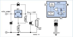
I'm thinking of something like this:

They are quite small but you do still need to ensure the voltage fed into it is fairly stable.

Brian.
Regarding the transformer, such mini audio interstage transformers have an iron core http://img.tradeindia.com/fp/1/001/175/371.jpg wouldn't they be ok for low current drawing at 50-60Hz? Or maybe a 600:600 modem transformer. These are small to fit inside the tube body. But will this solve the problems with the filaments mentioned above? I think that yes, because there is a real resistance at the windings. However on series filaments sets, one would expect all the filaments to run on the same current. And the transformer current will be different from that of the tubes filaments.

Regarding the "instead of taking one side of its output" comments, this gives me an idea, that of the virtual ground. How about connecting the bridge outputs to two series capacitors. One will serve as a negative end and the other as positive. In the middle point of the capacitors, it will be the virtual ground. Is is this virtual ground that will then be used for the eye. Will it do any good or am I thinking nonsense here?
--- Updated ---

Regarding the transformer, such mini audio interstage transformers have an iron core http://img.tradeindia.com/fp/1/001/175/371.jpg wouldn't they be ok for low current drawing at 50-60Hz? Or maybe a 600:600 modem transformer. These are small to fit inside the tube body. But will this solve the problems with the filaments mentioned above? I think that yes, because there is a real resistance at the windings. However on series filaments sets, one would expect all the filaments to run on the same current. And the transformer current will be different from that of the tubes filaments.

Regarding the "instead of taking one side of its output" comments, this gives me an idea, that of the virtual ground. How about connecting the bridge outputs to two series capacitors. One will serve as a negative end and the other as positive. In the middle point of the capacitors, it will be the virtual ground. Is is this virtual ground that will then be used for the eye. Will it do any good or am I thinking nonsense here?
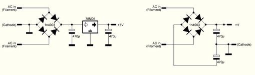
About the virtual ground I mean something like the schematic on the right. (on the left there was the real ground one)

The chassis ground and the eye circuit ground are isolated (at least on DC). The "grid" voltage that fed to the solid state eye, is now referenced to the virtual ground. This means that it will be half, from 6v to 3v. I can bring my circuit to work down to 3v, this is not a problem.

But will it work now and avoid the limitations we discussed above? (different filament configurations)?
 

Attachments

  • Capture.JPG
    Capture.JPG
    36.1 KB · Views: 80
Last edited:

such mini audio interstage transformers have an iron core... wouldn't they be ok for low current drawing at 50-60Hz?

Sufficient bulk of metal must be in the core...
Otherwise the transformer has a tiny Henry value allowing the primary to admit massive destructive current from mains.

The smallest power transformer I saw at Radio Shack is 6.3 VAC @ 300mA. Suitable for stepping down house voltage to drive one tube heater filament.

Notice the term is power transformer. Its primary winding is built with the proper values of both Henry value and ohmic resistance, so it has a resulting overall impedance enabling it to tolerate house voltage. It avoids drawing destructive current with normal load, or no load.
 
Last edited:

Sufficient bulk of metal must be in the core...
Otherwise the transformer has a tiny Henry value allowing the primary to admit massive destructive current from mains.

The smallest power transformer I saw at Radio Shack is 6.3 VAC @ 300mA. Suitable for stepping down house voltage to drive one tube heater filament.

Notice the term is power transformer. Its primary winding is built with the proper values of both Henry value and ohmic resistance, so it has a resulting overall impedance enabling it to tolerate house voltage. It avoids drawing destructive current with normal load, or no load.
I see
However remember, this is not mains transformer neither step down. It is just an isolation transformer 1:1 rated at 100mA (measured 65mA in my actual prototype but I leave some headroom). I am thinking also for these modem 600:600 ohm transformers as they are available in different small sizes
 

I would concur that audio transformers are not a suitable alternative and are probably more expensive too. Expect winding resistances far too high to supply enough current and cores more suited to higher frequencies.

The schematics you show are both valid but only in specific circumstances. For a generic tube replacement you have to think not of how to extract the heater voltage but what else is connected to it. Think what would happen if you linked one of the output sides to chassis and one of the input sides also to chassis or to some other voltage. In some hum cancellation circuits you may find a potentiometer across the heater connections with its wiper connected to chassis, think what might happen to it if the resistance to one end of the track was very low, it could easily burn out.

Brian.
 

Think what would happen if you linked one of the output sides to chassis and one of the input sides also to chassis or to some other voltage. In some hum cancellation circuits you may find a potentiometer across the heater connections with its wiper connected to chassis, think what might happen to it if the resistance to one end of the track was very low, it could easily burn out.

Brian.
>>>Think what would happen if you linked one of the output sides to chassis and one of the input sides also to chassis or to some other voltage.

Why should I do that Brian?
The second circuit has an isolated ground (at least for DC, or I could use small caps for 50Hz isolation too).
This means that my eye circuit ground is not connected to the chassis anywhere. It does not matter if the eye tube was right at the end of the filament tubes series connection with one of it's heater pins tied to the radio chassis ground.
Measuring on that configuration is done between the -V (grid pin, input to the circuit) and the VIRTUAL ground, not the chassis. Am I missing something here?

>>>In some hum cancellation circuits you may find a potentiometer across the heater connections with its wiper connected to chassis, think what might happen to it if the resistance to one end of the track was very low, it could easily burn out.

Well, I could use some low value resistors in series with both bridge AC terminals. This would interfere with any possible potentiometer noise cancellation, but at least it will protect the pot from burning. This will also add a bit of resistance, to "emulate" the resistance of the heater that was supposed to be in place. The value of course depends on each radio and what tube it expects to be connected in the eye, but I could measure the hot resistance of the most common ones and roughly decide on a value. This will make sets with series filament connection pretty much happy I guess.

What do you think on these 2 points?
It can never be perfect, just good enough to work.
 

Why should I do that Brian?
I'm not saying you would, but you seem to suggest this is a generic 'drop in' replacement for the tube so how the heaters are wired would depend on the individual radio design.

Personally, I wouldn't add any series resistance to emulate the heater, all it could do is produce additional heat. A typical original heater would be 6.3V 0.3A so consuming almost 2 Watts. Less load on a parallel circuit is generally a good thing.

A further point, if you use an isolated DC-DC converter, you can get ones with 12V output for 5V input and you can get ones with dual isolated outputs so you can create positive and negative supplies from a single component. They easily fit inside an octal base along with rectifier and reservoir capacitors.

Brian.
 

    neazoi

    Points: 2
    Helpful Answer Positive Rating
I'm not saying you would, but you seem to suggest this is a generic 'drop in' replacement for the tube so how the heaters are wired would depend on the individual radio design.

Personally, I wouldn't add any series resistance to emulate the heater, all it could do is produce additional heat. A typical original heater would be 6.3V 0.3A so consuming almost 2 Watts. Less load on a parallel circuit is generally a good thing.

A further point, if you use an isolated DC-DC converter, you can get ones with 12V output for 5V input and you can get ones with dual isolated outputs so you can create positive and negative supplies from a single component. They easily fit inside an octal base along with rectifier and reservoir capacitors.

Brian.
These DC-DC converters seem good. I wonder how they provide this isolation internally.

About the first point, do you think the virtual ground solution will work in eliminating these problems with the heaters? I know it is a kind of general thing, but does my thought seem correct?
 

As far as I can understand, only a transformer will provide total isolation and cure all the problems with the different heaters configuration, right?

I also found another alternative, if a small transformer cannot be found and this is isolation of the bridge with capacitors.
So in place of the filament, a small resistor and across it, two capacitors to drive the bridge. It might work actually, although not so efficient, but smaller size for sure.
 

Attachments

  • isolation.JPG
    isolation.JPG
    64.1 KB · Views: 82

The NME series DC-DC converters are very similar to the MAX256 and have tiny ferrite transformers and Schottky rectifiers inside them so they provide true isolation between n put and output sides. The problem with the MAX256 approach is it needs a DC supply of between 3V and 5V to operate so you still have the problem of creating that from the heater AC. It also has the issue that it's internal oscillator runs at about 1MHz so unless you provide a better alternative one and/or shielding, it is likely to cause interference in the radio bands.

I'm not sure it would be smaller in size, the MAX256 needs a heat sink to run at moderate to high loads and that means a PCB heat spreader as it has a bottom pad to carry the heat away. I doubt you will find a smaller solution than NME modules.

Brian.
 

    neazoi

    Points: 2
    Helpful Answer Positive Rating
To reduce mains AC amplitude via capacitive drop is feasible though risky. The capacitor must be non-polarized. Either place two electrolytic type back-to-back, or solder a gang of ceramics (100nF) in parallel.

The load can be:
* tube heater
* transformer
* full diode bridge
* diode & 6V zener diode filtered to yield regulated DC

reduce 120VAC via 2 caps 10uF draws 300 mA.png
 

    neazoi

    Points: 2
    Helpful Answer Positive Rating
To reduce mains AC amplitude via capacitive drop is feasible though risky. The capacitor must be non-polarized. Either place two electrolytic type back-to-back, or solder a gang of ceramics (100nF) in parallel.

The load can be:
* tube heater
* transformer
* full diode bridge
* diode & 6V zener diode filtered to yield regulated DC

View attachment 174171
That's very interesting to know!
However, this will not work in series heaters connection. There must be AC flowing in and out of the circuit in series. Also there is no need to reduce AC here
 

An electronic engineer friend told me that he has successfully used common mode chokes in the past, connected as transformers to get usable AC currents.
The advantage is that they can exist in very small sizes. Either this works, or not, I fear that if I connect such low-ohms primary in place of the filament, I might damage the radio.
If the filaments are wired in parallel, this low-ohms primary will actually short the transformer.
If the filaments are wired in series, the low-ohm primary will actually short the filament contacts in the tube socket and cause increase in filament voltage for all the other tubes.
What is your opinion on this?
 
Last edited:

Your assumptions about common mode chokes are correct. They are intended to limit the passage of high frequencies while not impeding 50Hz/60Hz so to use them at those frequencies would present almost a short circuit.

The floating ground will work but if the receiver uses hum cancellation circuits, the extra and possibly partially rectified currents it draws will imbalance the 'anti-hum' voltage.

I'm still not sure how your device works. If the floating ground is one side of the circuit supply but the voltage you are measuring is referenced to chassis and they are at different potentials there will be some difference between them that has to be added or subtracted from the measurement and it could carry some of the AC waveform.

Even the smallest transformer or common mode choke will be bigger than one of the DC-DC converters I mentioned. The photograph shows their size relative to other components, it's a shot taken of the inside of the Audio/Video switch on my web site.

Brian.
20220202_084728a.jpg
 

    neazoi

    Points: 2
    Helpful Answer Positive Rating
Your assumptions about common mode chokes are correct. They are intended to limit the passage of high frequencies while not impeding 50Hz/60Hz so to use them at those frequencies would present almost a short circuit.

The floating ground will work but if the receiver uses hum cancellation circuits, the extra and possibly partially rectified currents it draws will imbalance the 'anti-hum' voltage.

I'm still not sure how your device works. If the floating ground is one side of the circuit supply but the voltage you are measuring is referenced to chassis and they are at different potentials there will be some difference between them that has to be added or subtracted from the measurement and it could carry some of the AC waveform.

Even the smallest transformer or common mode choke will be bigger than one of the DC-DC converters I mentioned. The photograph shows their size relative to other components, it's a shot taken of the inside of the Audio/Video switch on my web site.

Brian.
View attachment 174218

Brian, I am thinking that the transformer solution will have it's own problems apart from size. The primary DC resistance is fixed for each transformer, but because of my "general direct tube replacement" assumption, it would be very unpredictable and cause voltage increase or decrease in all the other filaments in the radios if they are wired in series. If I wanted to focus only to replace one tube tube, such as the 6E5 for example, things would be much easier.

My bridge thinking on the other side won't work at all at series filaments, because power cannot pass from one AC pole of the bridge to the other. Even if I connect a series resistor between the AC poles of the bridge, again I face the same problems as that with the transformer, of not knowing which resistor to use, for the required voltage drop. Unless again it is to replace a single tube type like the 6E5.

I see with interest your idea for using these isolated power supplies, but won't again face the same problems on unknown resistance on series filament connection?
The other thing I do not like on them is the switching type, I really believe that closely inside the circuits of an LW/MW radio this will leak all shorts of birdies and noises, which is definitely something not allowed.

I am thinking of all shorts of crazy ideas, even rotary transformers (2 motors back to back), although these have to be custom made at that small size, if they can at all.

I start to get out of options, it really seems very difficult to take the power out of the filaments.

Perhaps I should focus in taking the power out of the anode, which is already DC and drop it somehow to reasonable levels for the regulator to work, without inducing so much heat. That would be more straight forward and would work with all sets.
 
Last edited:

Hi,

I see why you don´t want DCDC converters.

But many other power sources are noisy, too.
The mentioned motor-motor solution for example: If they are DC motors then you have a lot of noise caused by the commutator. And if AC ... then you need to rectify it ... and a rectifier surely causes noise.

So the possible solutions are limited. In best case they have DC in and DC out without switching.
Like an incandescent light bulb and a PV cell. While this is a rather low noise DCDC converter, I doubt the size, effort, efficiency and cost is suitable.

Klaus
 

    neazoi

    Points: 2
    Helpful Answer Positive Rating
Hi,

I see why you don´t want DCDC converters.

But many other power sources are noisy, too.
The mentioned motor-motor solution for example: If they are DC motors then you have a lot of noise caused by the commutator. And if AC ... then you need to rectify it ... and a rectifier surely causes noise.

So the possible solutions are limited. In best case they have DC in and DC out without switching.
Like an incandescent light bulb and a PV cell. While this is a rather low noise DCDC converter, I doubt the size, effort, efficiency and cost is suitable.

Klaus
I agree with you, even the DC motor will induce noise, actually it might be more broadband depended on the tiny spark inside it.

Meanwhile I have found this, which gives me some nice ideas about feeding the voltage from the anode!
Maybe a 2 or three stage circuit for less heat. 50mA max, ok for my purpose.
There is also the LR-8 for up to 450v input, but this is limited to 10mA or so.
Maybe I could place 5-6 of them in parallel, connected to the same output, through isolation diodes. I think this might work ok?
Again, I will have to use an unknown resistor at the filaments of the replacement tube, so that the rest of the series filaments work.
AND, the anode current limitation of the radio is another obstacle.
I am starting to get out of ideas.
 

Attachments

  • High-Voltage-Regulator-Schematic-Circuit-Diagram.jpg
    High-Voltage-Regulator-Schematic-Circuit-Diagram.jpg
    27.5 KB · Views: 77
Last edited:

Hi,
Meanwhile I have found this, which gives me some nice ideas about feeding the voltage from the anode!

It is rather low noise, not switching.

The biggest problem with this circuit is that it dissipates a lot of heat.
And although the IC is able to give the required current ... this is only true for a low voltage difference between input and output .. because of power dissipation.

Let´s say you have a 6V ouput at 65mA and a 100V input then there is a voltage drop across the regualtor of (100V - 6V) = 94V. Multiplied with 65mA this results in about 6.1W power loss. (at about 0.4W output power)
A TO-92 package has a R-th_ja of about 130K/W. This means a temperature rise of 800 °C. It simply will explode.

With 100V input this circuit maybe is able to supply 3mA only.

BTW: every analog regulator will cause the same power dissipation (V_in - V_out) * I.
All analog circuits suffer from this.

Only a transformer, a switch mode supply ... or similar will have less power dissipation. (higher efficiency).
All use some (higher) frequency to operate. (The higher the frequency the smaller)

Klaus
 

    neazoi

    Points: 2
    Helpful Answer Positive Rating
Hi,


It is rather low noise, not switching.

The biggest problem with this circuit is that it dissipates a lot of heat.
And although the IC is able to give the required current ... this is only true for a low voltage difference between input and output .. because of power dissipation.

Let´s say you have a 6V ouput at 65mA and a 100V input then there is a voltage drop across the regualtor of (100V - 6V) = 94V. Multiplied with 65mA this results in about 6.1W power loss. (at about 0.4W output power)
A TO-92 package has a R-th_ja of about 130K/W. This means a temperature rise of 800 °C. It simply will explode.

With 100V input this circuit maybe is able to supply 3mA only.

BTW: every analog regulator will cause the same power dissipation (V_in - V_out) * I.
All analog circuits suffer from this.

Only a transformer, a switch mode supply ... or similar will have less power dissipation. (higher efficiency).
All use some (higher) frequency to operate. (The higher the frequency the smaller)

Klaus
I see, it seems impossible. Also due to the anode current limitation.

The more I think of it the more I find this circuit interesting for feeding it from the filaments side.
It is an ordinary virtual ground system, but there is a (power) resistor between the bridge terminals.

Either on parallel or on series filaments connection, the AC voltage is taken at the resistor terminals, whereas at the same time provides a current flow through the resistor, for the rest of the radio filaments to turn on (in series connection).
Even if one end of the filaments is grounded (last series tube in the circuit) it would not matter.
Even if a hum-reducing pot is connected it would also not matter too much.
The noise out of the switching diodes, is not something I would consider too much as we are mainly talking about indirect heated filaments here, at 50Hz (or 60) and with the filtering capacitors in place.

The lower VCC available at the output (from a 6vAC input) is not of a problem, because I can make my indicator circuit work down to 3v by tweaking it. The input voltage to the indicator to be measured, will be referenced not to the chassis ground, but to this isolated ground between the 2 capacitors. Again my indicator has lots of headroom for tweaking this, so half voltage levels is not a problem.

The resistor value remains a problem, but I believe that the resistance of a heated filament of an ordinary 6v or 12v tube is more or less close for many tube types (just an assumption). Their current is mostly 300mA or so. on a 6 or 12v tube, and the tube heaters have usually a big tolerance, especially if the connection is in series.
 

Attachments

  • Capture.JPG
    Capture.JPG
    103.7 KB · Views: 71
Last edited:

Just a thought: Still use the DC-DC converter idea because it is simple and inexpensive. They are not noisy, I use them in sensitive receivers, video mixers, audio mixers and other things with no problems.

To extract the isolated input voltage, use a bridge rectifier but instead of a resistor to simulate the heater, use a constant current load. With a transistor, two resistors and a Zener diode you can make a crude voltage stabilizer that also passes a defined current. Place it on the DC side of the bridge of course. Rely on the collector current being constant if base to emitter voltage is fixed. It will dissipate the same heat as the original heater would, about 2W and it would work in a parallel or series heater chain.

Brian.
 

    neazoi

    Points: 2
    Helpful Answer Positive Rating
To extract the isolated input voltage, use a bridge rectifier but instead of a resistor to simulate the heater, use a constant current load. With a transistor, two resistors and a Zener diode you can make a crude voltage stabilizer that also passes a defined current. Place it on the DC side of the bridge of course. Rely on the collector current being constant if base to emitter voltage is fixed. It will dissipate the same heat as the original heater would, about 2W and it would work in a parallel or series heater chain.

Brian.
How will this work on a series configuration? The diodes in the bridge will prohibit AC to pass through.

If there was a small AC motor that would really solve all the problems. Or is it...?
 
Last edited:

Status
Not open for further replies.

Similar threads

Part and Inventory Search

Welcome to EDABoard.com

Sponsor

Back
Top