Continue to Site

Welcome to EDAboard.com

Welcome to our site! EDAboard.com is an international Electronics Discussion Forum focused on EDA software, circuits, schematics, books, theory, papers, asic, pld, 8051, DSP, Network, RF, Analog Design, PCB, Service Manuals... and a whole lot more! To participate you need to register. Registration is free. Click here to register now.

60MHz clock generation

Status
Not open for further replies.

raguna

Junior Member level 3
Joined
Apr 23, 2010
Messages
30
Helped
4
Reputation
8
Reaction score
4
Trophy points
1,288
Location
Earth
Activity points
1,540
Hi all!
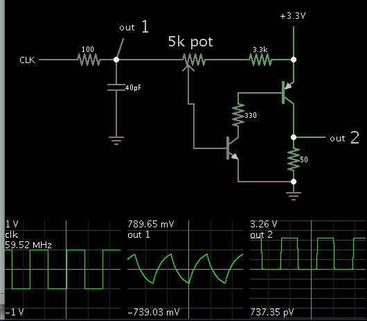
How can I generate a (0 to 3.3V) 60MHz sharp edge clock. I can get upto 100MHz sine wave with my function/signal generator. If I use any high speed comparator, there is always an offset( around 0.2V) at the output. Can I have some option/methods for its generation.

Thanks
 

Hi,
Try voltage controled oscillator..
it will produce the frequency you want ..
and you can customize it easily..

Thanks
 

I have simulated a clipping circuit by using a 60MHz 8Vpp sine wave and clipping it using 1N914 diodes at 3.3V, to generate approximately 3.3 VDC square wave. But, when I tried the same with my function generator and PCB, I see that 8Vpp sine is attenuated at that frequency and the does not clip at all. I noticed that the BNC-BNC wire has a huge capacitance ~40pF. Can some one suggest me to solve this issue.
 

Put an inductor in parallel with the cable to tune the capacitance out, Try 15 turns around a 4mm former as a starting point. swing the generators frequency and see where the voltage peaks, adjust number of turns to get it to 60 MHZ.
Frank
 

A comparator should not have a significant offset at its output. What comparator are you using?

What is the maximum rise and fall time you can live with?
 

Put an inductor in parallel with the cable to tune the capacitance out,
chunckey,Did you mean the implementation of the inductor in the picture below?If my assumption is right, why the inductor can tune the capacitance out?
Thank you so much.
inductor.JPG
 

One or two transistors can restore the rectangularity of the signal.

They must be chosen for capacity to respond at 60 MHz.

Two are used in the simulation. You may get by with one transistor if you fiddle with values.


The potentiometer alters duty cycle, by shifting the bias level.
 

Status
Not open for further replies.

Part and Inventory Search

Welcome to EDABoard.com

Sponsor

Back
Top