magpal
Newbie level 2
Hi,
I'm designing an integrated amplifier for wireless communication at 57-64 GHz with a SiGe BiCMOS process (but only using bipolar npn transistors). The tools used are Cadence Virtuoso with Spectre for simulation. I have no experience designing high frequency electronics.
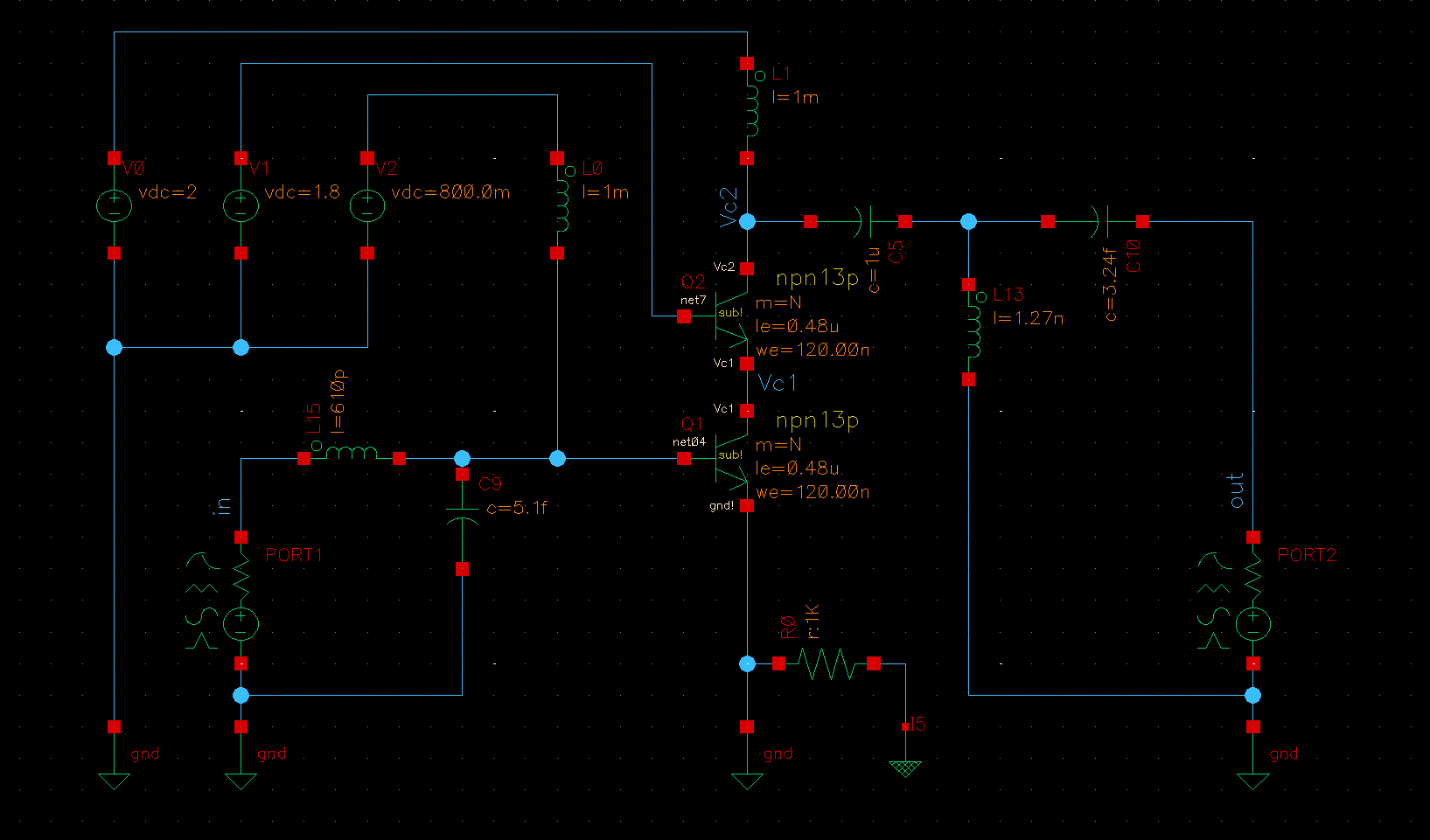
With a cascode (CE-CB) topology the simulated output reflection coefficient S22 have an extremely low resistance and very high reactance, in the Smith chart it's placed to the far right. See attachments "CECB_schematic" and "CECB_nomatch" for the schematic and the simulated s-parameters respectively. The transistors in the simulated circuit are small; multiplier m=1, number of emitters Nx=1, emitter length le=0.48um (can only be 0.48u and 0.84u).
This means that when impedance matching the output, the Q-factor is terrible as seen in the attached "CECB_Lmatch". A simple L-network was used, but attempts with T- and pi-networks hasn't shown any improvement. I regard the initial S22 as "unmatchable" for a reasonable Q and I imagine there is a step in the design procedure before impedance matching that I'm missing.
Does anyone have any thoughts on how to fix this? I'm guessing biasing, multiplier, emitter lengths etc., but I've seen no improvement in my attempts to vary these parameters. Any help will be much obliged.
I also attached "CECB_DCsweep_nomatch" where the bias voltage of the input transistor is swept for an unmatched circuit.
Thanks.


I'm designing an integrated amplifier for wireless communication at 57-64 GHz with a SiGe BiCMOS process (but only using bipolar npn transistors). The tools used are Cadence Virtuoso with Spectre for simulation. I have no experience designing high frequency electronics.
With a cascode (CE-CB) topology the simulated output reflection coefficient S22 have an extremely low resistance and very high reactance, in the Smith chart it's placed to the far right. See attachments "CECB_schematic" and "CECB_nomatch" for the schematic and the simulated s-parameters respectively. The transistors in the simulated circuit are small; multiplier m=1, number of emitters Nx=1, emitter length le=0.48um (can only be 0.48u and 0.84u).
This means that when impedance matching the output, the Q-factor is terrible as seen in the attached "CECB_Lmatch". A simple L-network was used, but attempts with T- and pi-networks hasn't shown any improvement. I regard the initial S22 as "unmatchable" for a reasonable Q and I imagine there is a step in the design procedure before impedance matching that I'm missing.
Does anyone have any thoughts on how to fix this? I'm guessing biasing, multiplier, emitter lengths etc., but I've seen no improvement in my attempts to vary these parameters. Any help will be much obliged.
I also attached "CECB_DCsweep_nomatch" where the bias voltage of the input transistor is swept for an unmatched circuit.
Thanks.