Continue to Site

Welcome to EDAboard.com

Welcome to our site! EDAboard.com is an international Electronics Discussion Forum focused on EDA software, circuits, schematics, books, theory, papers, asic, pld, 8051, DSP, Network, RF, Analog Design, PCB, Service Manuals... and a whole lot more! To participate you need to register. Registration is free. Click here to register now.

5v to run a 12v electronic relay?

Status
Not open for further replies.
I just read your thread from last year and saw the schematic.

The biggest problem is the Astable Multivibrator is incorrectly designed. http://www.zen22142.zen.co.uk/ronj/rt5.html
The Cap, C1 switches full scale Vcc on one side and the other side then exceeds the supply rail Vcc or Vdd since there is still a residual threshold voltage.
This then activates the internal overvoltage protection diodes which partially discharge the cap with excess current from the driver and can possibly blows the internal diode (fused open) which would alter the decay time and remove the protection..

This design is **not acceptable** for reliable operation in addition the risk of the above can trigger CMOS SCR latchup (shoothru catastrophic failure and fry the chip across the rails.)
rt5.png


A better Astable is as follows;
135-11423.png


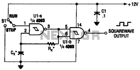
instead of the switch use your thermistor sensor with gate to act as the switch. ( several ways to do this)

The 74HC132; 74HCT132 is a quad 2-input NAND gate with Schmitt trigger inputs
 
Last edited:

Try something like this :

View attachment 90137

I want to analysis the operation mechanism of the circuit
i made simulation to note how much volt will be devolved across the coil with power supply 6V and input voltage to NPN transistor 1.5.
Suppose if the 1.5V is not applied to the NPN transistor and transistor is in off mode and in accordance the PNP is alsoe in off mode, then the capacitor will charge via 2.2K and bottom diode. if 1.5V applied to the NPN transistor, then the transistor will be ON and the capacitor will discharge across the NPN transistor because the terminal C and E has small resistance and E terminal connected to the ground.
In the opposite side the PNP transistor is in ON sate and the current will flow through the coil to the bottom diode to the ground.
My question is how at least 10 volt developed across the coil as mentioned in the text in the picture??
and why the bottom diode exist in the circuit?
 

My question is how at least 10 volt developed across the coil as mentioned in the text in the picture??
and why the bottom diode exist in the circuit?

It seems you have hijacked Sunny55's thread but somewhat related as I said "Sunny55 You cannot activate a 12Vdc relay with 5V... The pull in is 9V"

But thats OK

the 1N4148 drops 0.6V at low current but 1V at high current. the NPN Vce is ~>0.6V drop the PNP Vce is slightly higher due to lower drive current.

Whn NPN is off. Vcap is 6-0.6=5.4V via 2K2 & bottom diode.
When NPN is 1st driven ON, The PNP pulls the coil + side to 5.4V while the NPN drives the coil - side to 0.6 -5.4 = -4.8 thus the differential voltage is 5.4 +4.8 = 10.2V approx. via Vcap and two Vce drops. It works like a charge-pump , voltage-doubler transient pulse. Both diodes are off now.

As the cap discharges to meet the bottom diode forward holding current voltage of ~<1V the Coil sees about 4.5V holding voltage.

Now not all relays are the same. But the best use a "must switch" threshold of 2/3 of coil rating or 9V and "may release" at 1/3 or 4V but "must release" at "1/10 rated voltage" or 1.2V so 10V pulse only needs to be long enough to switch the relay ON and then the PNP holds it in place with 4.5V.

When switched off the TOP diode does its anti-kick clamp to protect the PNP Vce.
 
  • Like
Reactions: andro

    andro

    Points: 2
    Helpful Answer Positive Rating
It works like a charge-pump , voltage-doubler transient pulse. Both diodes are off now.

As the cap discharges to meet the bottom diode forward holding current voltage of ~<1V the Coil sees about 4.5V holding voltage.

Hello SunnySkyguy
So i understood that, the capacitor pumps with opposite voltage to the coil for a short time at starting of NPN transistor goes on and after that the capacitor discharges through the NPN transistor because it has low resistance, means you just need pulse for pushing the coil up for short time period and hold it at 4.5 by transistor PNP. But you consider the Vce ~0.6 V because it is near to saturation mode?

Thanks for replay
 

Status
Not open for further replies.

Similar threads

Part and Inventory Search

Welcome to EDABoard.com

Sponsor

Back
Top