Continue to Site

Welcome to EDAboard.com

Welcome to our site! EDAboard.com is an international Electronics Discussion Forum focused on EDA software, circuits, schematics, books, theory, papers, asic, pld, 8051, DSP, Network, RF, Analog Design, PCB, Service Manuals... and a whole lot more! To participate you need to register. Registration is free. Click here to register now.

[SOLVED] 5V 500mA from 5V 2A ????

Status
Not open for further replies.

Jigar 4 Electronics

Full Member level 5
Full Member level 5
Joined
Apr 28, 2011
Messages
312
Helped
40
Reputation
82
Reaction score
38
Trophy points
1,318
Location
Hamilton, ON, Canada
www.facebook.com
Activity points
3,368
Hello Everyone,

I've an ESC (Electronic Speed controller) for my motor.
That ESC provides BEC (battery eliminator Circuit) of 5V 2A.
I want to use this to get 5V 500mA.

Could you please help me with this? how can I make a current limiter?

I don't have any other option to get 5V 500mA. Please help.

Thanks for your time.
 

You can try with LM317 as current limiter.

attachment.php
 

this you can simply achieve using one transistor that having max rating 500mA
by creating a constant current source
just apply 5v ,2A to its collector and give feed back to base
and take out put between emitter and ground
Note: for selection of transistor yuo have to take care
other wise your transistor get heated up and burned
if you want the circuit diagram i will posted here
but befor that you should tell me what type of load you are using
 

I don't think this is possible without complicated electronics. What is being asked for is a current limiter that doesn't drop any voltage until the limit is reached. Even nikhilt007's idea won't work because it drops at least Vbe of the transistor which at 0.5A may be 0.7V or more.

I see the only solution as being a resitor in series with the output with a value so low that it doesn't significantly affect the load and with a monitoring circuit across it to control the output voltage/current. Even that method has some impact on the output.

I suspect the OP isn't specifying their needs very well and with more information there might be a simple solution. Why is a speed controller feeding a battery eliminator in the first place and is the OP confusing the maximum current rating with the actual current their circuit needs?

Brian.
 

yes I can, but the input voltage to the LM317 must be greater than the output voltage.
so I am not able to use it.

Thats true if we speak about voltage regulation, in contrast of that this is LM317 in current limiting configuration, and you can use it. Its simple to try.
 

Thats true if we speak about voltage regulation, in contrast of that this is LM317 in current limiting configuration, and you can use it. Its simple to try.

I haven't done a hardware test but it seems impossible to have a 0v drop across the LM317 , how can the internal pass element have 0v drop?
Have you tested it and you get 5v out for 5v in?
 

Using an LM317 in constant current mode would not work for two reasons:
1. It's constant voltage thats asked for - with a current limit, not constant current.
2. It generates constant current by dropping a fixed voltage across the load resistor. So even if the LM317 didn't have a voltage overhead of it's own, it would still have to drop Vref (1.25V) across the resistor.

Brian.
 

I think the best case scenario would be with a low Rds-on mosfet as a series pass element and and a very small shunt resistor (like 20mohm), then with a couple of opamps amplify the voltage across the resistor and drive the mosfet to limit the current to the set value.

Something like
curr_limit.gif

U1:A works as a differential amplifier with a gain of 50x giving output 1v/A , U1:B works as a comparator getting a reference voltage from R6/R6 set to 0.5v.
 
I've an ESC (Electronic Speed controller) for my motor.
That ESC provides BEC (battery eliminator Circuit) of 5V 2A.
I want to use this to get 5V 500mA.

Could you please help me with this? how can I make a current limiter?

I don't have any other option to get 5V 500mA. Please help.
There's a basic conflict in your request. You can regulate voltage or regulate current, but you can't do both simultaneously. If you want to limit the current, then that means you would need to reduce the voltage.

What exactly is the load requirement? Is it designed to operate from a voltage source or from a current source?
 

What are you trying to power? If it is a device that needs 500mA, that is all it will draw from your 2A supply you don't need anything else.
 

I found the following explanation related to what he described
en.wikipedia.org/wiki/Battery_eliminator_circuit

If this is just about detecting when the current has dropped below the threshold then in the circuit I have provided remove the mosfet and just use the shunt resistor with the opamps to get a flag signal.
It would be better to use a ref. voltage device rather than a simple divider.
 

Can you not modify the original power supply? Surely, it must have some sort of current limiting that can be altered to
only allow 500mA?
 

thanks for your confirmation
the circuit i suggested will give an otput violtage of 4.5v
most of the ics rated 5v will work on 4.5v thats why i asked him what type of load/ device he want to connect
i think by applying resistor series to drop out current then your voltage also will reduce
correct me if i am wrong
 

I had the same thought as pilko, what are you trying to power? If your circuit calls for 5V at 500mA, that just means that is how much current it will draw (normally). If you connect it to a 2Amp power supply, it will still only draw what it needs (500mA). Think of it this way, my house has a 300Amp service. If I turn everything off in the house except a 100Watt light bulb, that light bulb is not going to draw 300Amps. It will draw the amount of current it needs. If there is a concern that your circuit may draw more then 500mA (possibly due to a fault of some kind), just put a 500mA fuse between the power supply and your circuit.
 

I think he mentioned motor in thread first post. What happens with current when motor starting (inrush current) ? I think he wants to eliminate that, and eliminate that shocks on power source.
 

Sorry to all of you to giving late reply... actually I was not in touch with internet for a whole day.


From tpetar :

TPS62000DGS

Figure 7 on page 32
https://www.ti.com/lit/an/slyt118/slyt118.pdf

Thanks, that could be the good solution, I'll try it for sure.

@alexan_e, Thank you for that circuit sir. I'll try it tomorrow as all components are ready for me.

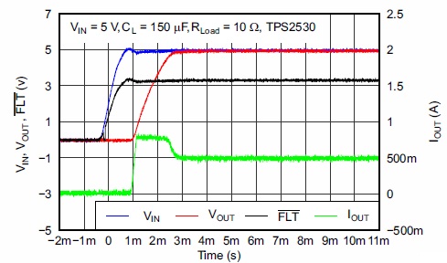
@tpetar, IC TPS2530 could be an solution too... I've refer it's datasheet.
It provides below graph which says that Vout & Vin can be 5V with 500mA Iout, but the load is of 10ohm only, But I'll still make a try with it.
7408352900_1361813881.jpg


And let me clear my question with some more details.
I've a LiPo Battery as a source 14.8V, 5A, with 30C discharge rate.

I am connecting it to ESC to drive my motor properly.
That ESC is providing me a Battery Eliminator circuit which acts as an source of 5V 2A.

I want to drive my controller board which requires 5V 100mA + USB Camera & Pendrive which require 5V & around 200-300 mA.
These all will be fed by BEC (I've no other option).

so if I get 5V 500mA (300mA to 700mA would also be prove beneficial), then it'll be best for me.

Still now I've get TPS60130 as a good result for this problem.

Thank you so much to all of you to providing your ideas.
Please help me with any further ideas.
 

Status
Not open for further replies.

Part and Inventory Search

Welcome to EDABoard.com

Sponsor

Back
Top